Railway Bridge Design: Fascinating, Ever Changing
Written by Gary T. Fry, Vice President, Fry Technical Services, Inc.; Railway Age Contributing Editor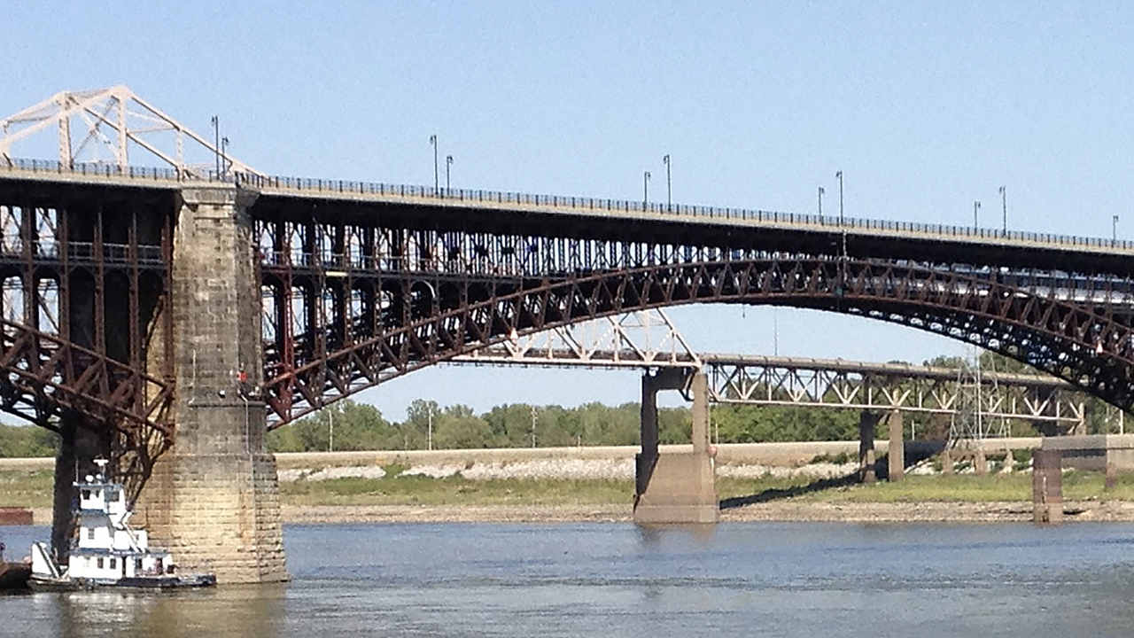
Figure 1: The Eads Bridge in St. Louis, Mo. Opened in 1874, it is the oldest bridge in active service over the Mississippi River. It carries both railway and highway traffic. (Courtesy of Gary T. Fry.)
RAILWAY AGE, JULY 2023 ISSUE: Welcome to “Timeout for Tech with Gary T. Fry, Ph.D., P.E.” Each month, we examine a technology topic about which professionals in the railway industry have asked to learn more. This month, our subject is railway bridges, specifically some of the methods railway bridge engineers use to ensure new bridges are safe, efficient and long lasting.
For many people, railway bridges fall into that category of objects around us that are so commonplace and familiar they often go unnoticed. We’ve been designing and building railway bridges for almost 200 years, and some of the oldest railway bridges still in service have been spanning successfully for more than 150 years. For example, Figure 1 (above) is the Eads Bridge spanning the Mississippi River at St. Louis, Mo. It carries railway and highway traffic. Opened in 1874, it is the oldest Mississippi River bridge still in service.
Given this long successful history, some might think that the process of creating a new railway bridge is trivial and uninteresting. For example, when an old railway bridge needs to be replaced, why don’t we just take the original design documents and build a new one just the same? After all, the original bridge lasted a really long time. Why spend time and money to do something different that might not be as good? These are great questions I have been asked many times in many different countries around the world, and I have some responses to offer.
Today, we stand on the shoulders of bold pioneering giants—the first generation of railway bridge designers and builders who solved what were then unprecedented problems. A few of them wrote books that detailed the problems they encountered and described their methods of solution. From this vantage point, we see more solution possibilities than at any time in the history of railway bridge engineering. Most important, we see better solutions.
We have the benefit of knowing the limitations, vulnerabilities and other improvable features of existing bridges because they exist. We have opportunities to observe them and learn from them. We have the benefit of access to careful assessments of the complete service lives of bridges and access to comprehensive research into strategies to enhance bridge performance and efficiency. Therefore, when a railway bridge needs to be replaced, it is an opportunity to apply lessons learned and deploy better solutions. It would be foolish to do otherwise—a fact recognized early on by American railroaders.
The mid-19th century witnessed the onset of extensive railway construction in the U.S. During the ensuing era of rapid railway expansion, the design and construction details of railway bridges and most other pieces of railway infrastructure varied considerably among railroads. In the late 1890s, a movement formed in the industry to develop a comprehensive digest of best-practice recommendations for building and maintaining railways. By 1900, the organization currently known as the American Railway Engineering and Maintenance-of-Way Association (AREMA) had formed and held its first annual convention at Steinway Hall in Chicago.
The primary mission of AREMA was to serve as a deliberative forum to develop technical best-practice recommendations for the railway industry based in mathematics, science, engineering, and, crucially, lessons learned from existing systems. Notably for our subject this month, three committees were established in AREMA’s earliest days to develop and maintain consensus best practices for railway bridges: Committee No. VII on Wooden Bridges and Trestles, Committee No. VIII on Masonry, and Committee No. XV on Iron and Steel Structures.
Many of you will recognize these three committees today as Committee 7–Timber Structures, Committee 8–Concrete Structures and Foundations, and Committee 15–Steel Structures. The members of these committees maintain chapters 7, 8 and 15 of AREMA’s Manual for Railway Engineering (MRE), the most comprehensive compendium of consensus best-practice recommendations for designing, building, operating and maintaining railway infrastructure in the U.S.
With that as introduction, how does one go about solving a railway bridge design problem? Let’s start with the essential nontechnical features. The practice of railway bridge design is an exacting, creative and open-ended process that benefits greatly from effective teamwork. For every bridge design, there exist infinite possibilities for acceptable solutions but also infinite possibilities for unacceptable ones. The design team’s priority is to make sure it is searching in the region of acceptable solutions. Then it can refine the search toward acceptable solutions that are also highly efficient to build and maintain.
At the end of the day, the team requires expertise, experience, energy, patience and fortitude. To arrive at the very best solutions, a design team must be both critical and affirming and committed to exploring the design space thoroughly, including solutions that might challenge convention.
Let’s imagine that we have a great design team with checks in all the right boxes. The essential technical work of the team is to ensure that each candidate design solution satisfies the “Three Ss”: Strength, Stiffness and Stability. We will discuss each of these in turn, starting with Strength.
The strength of a bridge is usually defined simply as the maximum loads that can be applied to the bridge in various patterns before the bridge or any of its components fail. To establish the strength of a bridge, detailed mathematical and empirical analyses are performed that generally consider the following:
- The materials used to make the bridge components.
- The shapes of the components.
- The geometric arrangement of the components.
- The arrangement of connections among the components.
The design objective is simply for the strength of the bridge to exceed its expected loading in service by reliably and statistically significant margins. Eminent structural engineer and educator Hardy Cross once suggested that a structure’s “strength is essential and otherwise unimportant.” His implication was that if a structure is not fundamentally strong enough for its load environment, nothing else matters. But if it is strong enough, there are other things to consider; for example, Stiffness and Stability. We consider Stiffness next.

(A) unloaded and (B) loaded. (Courtesy of Gary T. Fry.)
Figure 2 (above) shows drawings of a beam that is supported by blocks at each end. In Figure 2-A, the beam is not loaded. In Figure 2-B, the beam bends under a load applied at its center, and its supports also deform. The bend in the beam and deformation of its supports are measurable on a global scale. The stiffness of a structure is a measure of the amount of load that is required to cause a certain amount of displacement. A structure with a high level of stiffness will deform less than a structure with a lower level of stiffness.

(Courtesy of Gary T. Fry.)
Last but certainly not least, we consider the third S: Stability. The photograph in Figure 3 (left) shows a pencil balanced on its end. The pencil can be proved mathematically to be stable. Most of us, however, would consider the stability of the pencil to be precarious because we imagine it wouldn’t take much effort to cause the pencil to fall over—a draft in the air or a slight bump to the table.
Strict mathematical stability like this is often the sort of thing that we enjoy as entertainment in circus acts—like plates spinning on the ends of slender rods. We observe that the plates aren’t falling on the ground, but we anticipate that to be the natural outcome. We sense the plates remaining perched on the rods as an unnatural state.
Now, let’s consider stability not in a strict mathematical context, but in the context of a railway bridge. Design teams must develop an arrangement of connected structural members and bridge supports whose natural state is to remain solidly in that configuration, even when significant loads are applied to the structure. That is, the structure does not have any precariously balanced features analogous to the pencil in Figure 3.
Ensuring that this is the case often involves applying various combinations of simulated loads within a mathematical model of the structure as it exists in service. Such models have the capability of estimating the deformation of the structure under the actions of the loads. In simple terms, a structure is stable when specified patterns of loads with specified magnitudes cause deformations in the structure that are acceptably small. Referring to our previous description of stiffness, we see that there is a relationship between structural stiffness and structural stability. A structure must possess at least some minimum level of stiffness under all specified load patterns to be acceptably stable.
Despite a 200-year history, railway bridges continue to present design teams with ceaselessly fascinating challenges. At the beginning, the challenges were to discover basic solutions for effective railway bridge designs without the benefit of precedent. Today, the most significant challenges are to discover strategies that enhance the performance, efficiency and longevity of new bridges using lessons learned from their ancestors.

Dr. Fry is Vice President of Fry Technical Services, Inc. He has 30 years of experience in research and consulting on the fatigue and fracture behavior of structural metals and weldments. His research results have been incorporated into international codes of practice used in the design of structural components and systems including structural welds, railway and highway bridges, and high-rise commercial buildings in seismic risk zones. He has extensive experience performing in-situ testing of railway bridges under live loading of trains, including high-speed passenger trains and heavy-axle-load freight trains. His research, publication, and consulting have advanced the state of the art in structural health monitoring and structural impairment detection.