Rail and Wheel Fatigue Crack Defects Inspection Imperative
Written by Gary T. Fry, Vice President, Fry Technical Services, Inc.; Railway Age Contributing Editor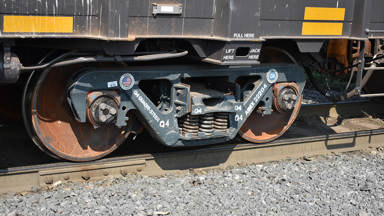
(William C. Vantuono Photograph)
RAILWAY AGE, JUNE 2023 ISSUE: Welcome to “Timeout for Tech with Gary T. Fry, Ph.D., P.E.” Each month, we examine a technology topic about which professionals in the railway industry have asked to learn more. This month, our subject is fatigue defects that form in railway wheels and rails.
Although this is prime material for a very thick volume (or two), our focus will be on a subset of safety-critical issues. Along the way, I will include a few brief callouts to related topics that hint at the breadth involved in these problems. Let’s get started!
In the January 2022 “Timeout for Tech,” I provided a general overview of metallic fatigue. The key takeaways were these: Fatigue cracks in steel are neither manufacturing defects nor the result of manufacturing defects. Rather, fatigue cracks in steel are a result of routine use in service. They are caused by repeated load applications that give motion to atomic-scale imperfections called dislocations.
Dislocations are misalignments present in the crystal lattices of all metals, including steel. Dislocations individually may be on the order of 0.00000004 inches in length, but they occur in great numbers. For example, one could expect to find 10 million miles of dislocations in a three-foot length of AREMA 136RE rail and more than 65 million miles in a single 36-inch freight car wheel—amazing!
At first thought, it might seem logical that eliminating dislocations would improve steel components—making them essentially fatigue-proof. Remarkably, however, it is dislocations that give steel alloys essential structural properties such as ductility and fracture toughness. Even if it were possible, eliminating dislocations would make steel uselessly brittle. So, we are left facing the simple fact that every component made from steel is vulnerable to producing fatigue crack defects under the action of repeated loads that mobilize dislocations. That gives us two basic conditions to assess.
Let’s consider railway rails and wheels. With certainty, we can say that they both experience repeated loads. Each full revolution is a load cycle for a wheel, and the passage of a wheel is a load cycle at each location along the length of a rail. Now, we must address the question of mobilizing dislocations. This condition is much more difficult to assess and has been an active area of research for nearly 200 years.
Dislocation motion in steel is caused by shearing distortions of crystal lattices beyond threshold limits that are determined through controlled testing. Fatigue cracks come from the accumulated and irreversible motions of the dislocations. To assess the fatigue vulnerability of components, the threshold values from testing are compared to values obtained from analysis models of the components, values from field measurements of the components under load, or both.
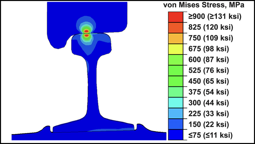
For example, Figure 1 (above) shows stress results from a computer model of rolling contact between a 36-inch freight wheel and an AREMA 136RE rail. The wheel load was just under 36,000 pounds, which is normal for current revenue service in North America. The form of stresses plotted in Figure 1 can be related directly to the stress-strain curve for the wheel and rail steel. In the peak zone, the stresses exceed the yield strength of both materials, which would generally be expected to fall below 120 ksi. Having the von Mises Stress exceed the yield strength of the steel by any amount means the peak stresses in the wheel and rail substantially exceed the threshold level needed to cause dislocation motion.
We have now established that both conditions for fatigue vulnerability of wheels and rails have been met. Wheels and rails in North American revenue service are repeatedly loaded at levels that are expected to cause dislocation motion. After some period of exposure to this service environment, we should expect to observe fatigue crack defects in both components. And, in fact, we do on a regular basis.
There are two additional questions to consider. How many miles can a wheel travel under a given load before producing a fatigue crack defect in the wheel? How many of those loaded wheels can pass over a rail before producing a fatigue crack defect in the rail? These questions are the subject of a specialized field called fatigue mechanics.
The best fatigue mechanic models are the critical-plane models, and among critical-plane models, the best are the strain-based approaches. With these, one can prepare detailed estimates for the expected wheel and rail fatigue lives at which end fatigue crack defects will be present. But there are substantial caveats to disclose. Notably, the predictions rarely agree with test results to an actionable level useful to decision-makers.
This is because fatigue test results always contain large variability. Tightly controlled laboratory fatigue tests contain substantial scatter, easily a factor of two or more, even when using specimens polished to a mirror finish. In the comparatively less controlled environment of revenue service, we should expect more variability—an additional factor of two, at a minimum. In combination, that’s a factor of at least four!
Let’s look at this in a simplified example. Using a model calibrated against test data, I might predict on average that wheels are expected to be defect-free for 15 years. Given the expected variability, however, some wheels might experience a fatigue failure after seven years or fewer. It can also go the other way. Some wheels might survive defect-free for 30 years or more. There are rigorous statistical methods to consider these issues, but the takeaway is the same. I cannot point to a wheel on a train and say exactly how long it will last before producing a fatigue crack defect, even if I know perfectly its entire past and future service history. The same is true for rails.
Though I might not know how long a given wheel or rail will last, I do know that it is at risk of producing a fatigue crack defect and where the defect is likely to form. I know this from modeling and from corroborating forensic investigations of wheels and rails that failed because of fatigue crack defects. Qualitatively, the models and forensics agree extremely well. They agree quantitatively only in a broad statistical context.
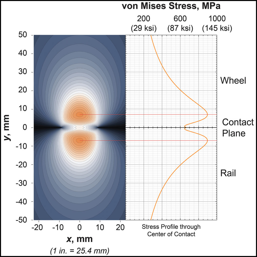
Now consider Figure 2 (above), which shows plots of the same stress function used in Figure 1. In Figure 2, we are focused on the peak stress areas immediately adjacent the wheel/rail plane of contact. The wheel is represented by the upper plots and the rail is represented by the lower plots. We see clearly that the peak stresses occur a little less than half an inch from their contacting surfaces. Fatigue models will tell us that is where the fatigue cracks will nucleate and experience early growth.
Once established, those cracks are substantial stress raising defects in the material that will continue to grow larger and potentially serve as nucleation sites for new fatigue crack defects. Unfortunately, we cannot see any of those cracks since they are contained with the steel. But we can detect them using ultrasonic transducers (UTs) before they become a size that will cause complete failure of the wheel or rail.
We have been inspecting rails using UT systems for more than 70 years. Currently, it is a requirement to inspect rail for these internal fatigue defects. In-motion systems have been perfected to make the inspections effective and efficient.
Consider Figure 2 again. Careful examination reveals that the fatigue behavior in the wheel near the contact plane should be nearly identical to the fatigue behavior in the rail near the contact plane—namely, formation of invisible internal fatigue crack defects. It is a clear example of Newton’s Third Law (translated from Latin): “Actions of two bodies on each other are always of the same nature and in opposite directions.”
Inexplicably, it is neither a requirement nor a common practice in North America to inspect wheels for internal fatigue crack defects—defects that are well-known to occur. Given these facts, one imagines UT inspection of wheels as “low-hanging fruit” to significantly reduce the risk of wheel failures and associated train accidents.
Inspecting both rails and wheels for internal fatigue crack defects is imperative to enhancing and ensuring the future safety of railway operations.
Reference:
Fry, Gary T. 2022. “Metal Fatigue: How Dangerous Fatigue Cracks Develop in Sound Steel.” Railway Age, January 2022, pp. 36-38.

Dr. Fry is Vice President of Fry Technical Services, Inc. He has 30 years of experience in research and consulting on the fatigue and fracture behavior of structural metals and weldments. His research results have been incorporated into international codes of practice used in the design of structural components and systems, including structural welds, railway and highway bridges, and high-rise commercial buildings in seismic risk zones. He has extensive experience performing in situ testing of railway bridges under live loading of trains, including high-speed passenger trains and heavy-axle-load freight trains. His research, publications and consulting have advanced the state of the art in structural health monitoring and structural impairment detection.