Wheel Profiles and Potential Switch Point Derailments
Written by Ulrich Spangenberg, Principal Investigator, and Matt Wenger, Senior Engineer, MxV Rail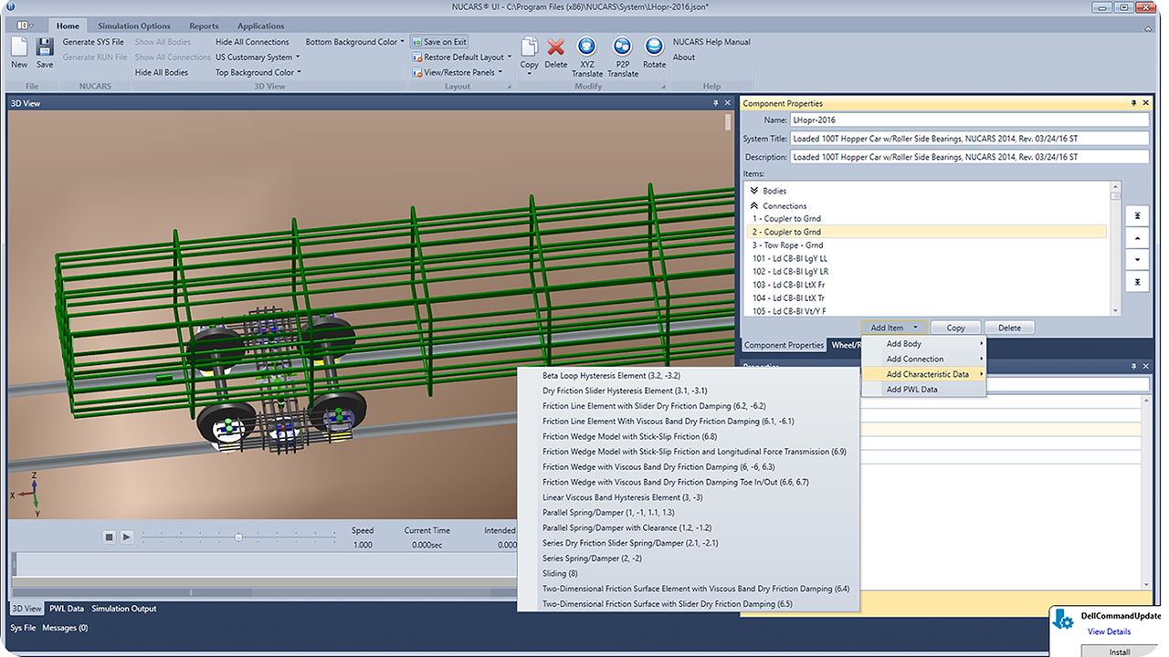
MxV Rail illustration
MxV RAIL R&D, RAILWAY AGE MARCH 2024 ISSUE: Turnouts in poor condition can increase the risk of a worn wheel with steep flange angle and acute flange tip metal flow getting wedged between the switch blade and the stock rail and causing a derailment. An example of this condition is depicted in Figure 1(a). Typical poor turnout conditions include the switch of a turnout being out of adjustment, or the switch point being gapped, worn, chipped, or broken.
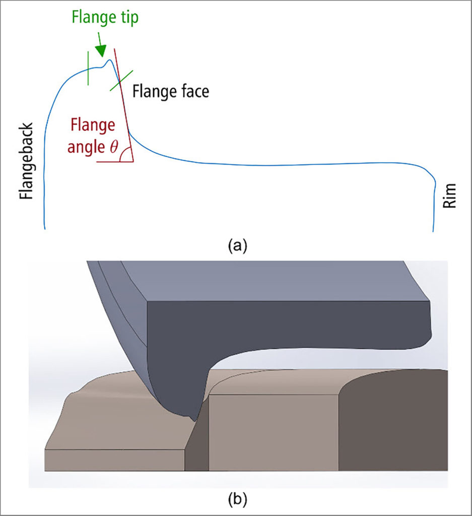
Figure 1: (a) Terminology describing the worn state of a wheel flange and (b) Wheel in (a) contacting the switch blade in a 3D computer-aided design (CAD) model
As part of the Association of American Railroads Strategic Research Initiatives Program, MxV Rail investigated the interaction between worn wheels and measured switch point rail profiles to assess the likelihood of a derailment when these profiles interact.
Methods
MxV Rail researchers obtained the Cartesian coordinates of 320,000 wheel profiles measured by a wayside wheel profile detector and calculated the minimum flange tip radius and maximum flange angle of these profiles. The team identified nine wheel profiles that had a minimum flange tip radius less than 0.1 inch (2.5 mm) and a maximum flange angle greater than 77.5 degrees.
Measured wheel profiles for those cars with one of the nine severely worn wheel profiles were used in NUCARS® analyses to calculate both the lateral wheelset displacements relative to the center of the track and the angles of attack at a point just before switch blade contact was made. The NUCARS® analyses were performed using an empty hopper car (part of the standard NUCARS® library) traversing the diverging route of a measured left-hand turnout with a 0.46-degree kink angle and a 39-foot-long switch rail length in the facing direction at 40 mph.
MxV Rail engineers developed 3D CAD models of the measured wheel profiles and the portion of the track leading up to and including the switch point. In these 3D models, the wheelset was constrained relative to the track with the lateral wheelset displacement and wheelset angle of attack determined by the NUCARS® analyses. The wheelset was moved longitudinally along the rail to find potential contact points that were assessed to determine the likelihood of a derailment.
Results and Discussion
Based on the NUCARS® analyses, engineers found that four wheelsets ran with a significant offset to the center of the track as they approached the switch point. Two out of the four wheelsets ran with an angle of attack typically associated with the negotiation of a 1- to 2-degree curve, thereby angling the flange tip radius toward the switch point. Figure 1(b) shows an example of interaction between one of these four wheels and the measured switch point. The measured switch point was in good condition and, in each of the nine investigated measured wheel profile cases, the acute flange tip metal flow did not become wedged between the stock rail and the switch blade point.
Conclusion
Worn wheels with an acute flange tip radius, often accompanied by a steep flange angle, were found to run with both a lateral offset from the center of the track and a noteworthy angle of attack. Contact between a worn wheel and the switch point rail profile did not show an increased risk of derailment for a switch in good condition.
References
Association of American Railroads (AAR) Manual of Standards and Recommended Practices, Section D, Trucks and Truck Details, M-976. 2019; 31–39.