Welding Physics and CWR
Written by Gary T. Fry, Vice President, Fry Technical Services, Inc.; Railway Age Contributing Editor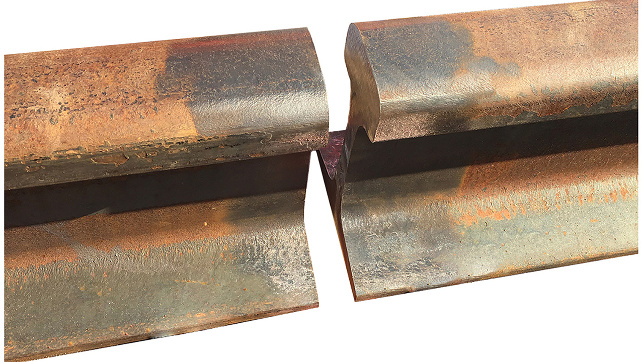
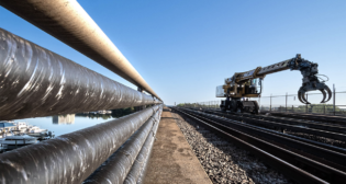
Figure 1. Joining lengths of rail is a fundamental problem in railway engineering. (Courtesy of Gary T. Fry.)
RAILWAY AGE, MAY 2023 ISSUE: Welcome to “Timeout for Tech with Gary T. Fry, Ph.D., P.E.” Each month, we examine a technology topic about which professionals in the railway industry have asked to learn more. This month our subject is continuous welded rail (CWR).
A fundamental problem in railway engineering is joining lengths of rail to form the contiguous track that trains need to operate (Figure 1). Especially over the past 50 years, welding has become the preferred rail joining method for both passenger and freight railways in the U.S. and most other nations with railways. This is despite the challenges of welding steel rail. Rail steels comprise alloys that are considered difficult to weld and reliably obtain acceptable mechanical properties afterward: strength; ductility; fracture toughness; and fatigue resistance. Two welding processes stand out in their ability to reliably join rails: Thermite Welding and Flash Welding. We’ll start with thermite welding.
Thermite welding of railroad rail traces its history to Germany at the end of the 19th century. German chemist Johann Wilhelm Goldschmidt discovered a process to produce pure metals through the chemical reduction of metal oxides using pure aluminum—the aluminothermic reaction. This reaction is exothermic and can be designed to generate substantial heat energy. The most common aluminothermic reaction used in rail welding generates 3,350 KJ of heat and reaches a theoretical maximum temperature of 5,600 degrees F. By the early 1920s, its application as part of a welding process to join railroad rails was established. Figure 2 is a photograph of a thermite rail weld in progress.
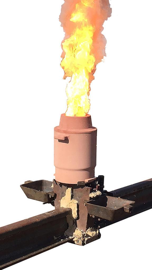
To make a traditional thermite rail weld, the two rail ends that will be joined are set apart with a 1-inch gap that is then enclosed by a refractory split mold. After preheating the rail/mold system with an oxy-fuel gas torch, a single-use refractory crucible containing the proper volumes of iron oxide, and aluminum particles (as well as steel filler material and other alloying and slag-forming materials) is placed over the open top of the molds. An ignition powder is used to provide the activation energy for the aluminothermic reaction. After a dwell time of 25 to 35 seconds in the crucible, molten steel fills the mold cavity and solidifies to join the rail ends.
With thermite welding, no external power source is required because the molten metal for the casting is produced by the aluminothermic reaction. A thermite rail weld can be completed by a team of two welding technicians in a little less than 45 minutes—even in remote territories. Because of its portability and ease of use, thermite welding is the most common method for completing repair welds on Class I railways in North America.
The second common process for rail welding is flash welding. Figure 3 is a photograph of a flash rail weld being performed at a rail welding production facility. Flash welding comprises three primary steps: flash, upset, and hold. In flash rail welding, the ends of two rails are aligned close together end to end and gripped by special hydraulic clamps. The clamps serve three purposes: hold the rail ends in alignment; apply electric power to the rails; and move the rail ends relative to one another to control the flash, upset, and hold steps of the welding process.
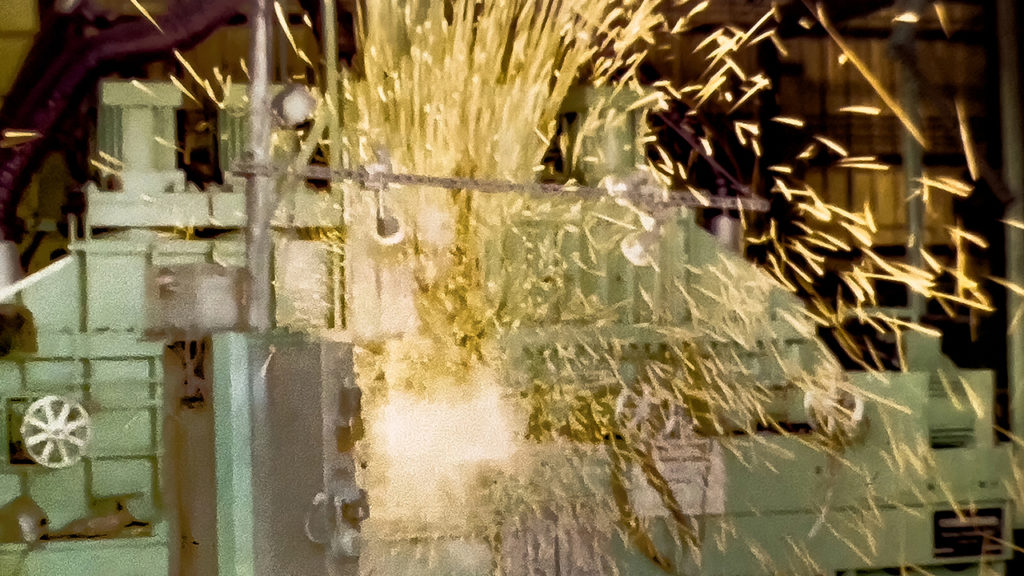
The flash step involves establishing an electric arc between the ends of the rails, which heats them to melting and expels metallurgical impurities from the joint. The upset step involves pressing the molten ends together under a controlled force, roughly 100,000 pounds, which results in a predictable amount of permanent deformation (or plastic upset) within the joint. During the hold step, a compressive force is maintained across the joint, but no further plastic upset occurs. The joint is held under force until it has cooled enough to ensure an acceptable weld has been made. Electric current of varying magnitude can be applied through the now-joined rail to control the cooling rate of the joint, thereby ensuring development of acceptable metallurgical and mechanical properties of the completed weld.
It takes roughly three minutes to complete a flash rail weld. Flash rail welding can be performed in a plant setting as seen in Figure 3, or in the field using equipment mounted on rail vehicles. There are numerous variations of flash rail welding process parameters and means of controlling them in real time during welding using digital sensing and digital feedback algorithms.
At first glance, these two welding processes seem unrelated to one another; just compare Figures 2 and 3. In fact, however, these two welding processes share as an end goal the essential principle that all welding processes have in common. That is, in its most basic form, welding is simply a process to establish metallic bonds and favorable metallurgy between two separate pieces made from the same (or very similar) alloys.
Our welding application involves two pieces of rail steel. Rail steels comprise more than 97% iron by weight. So, welding rail pieces together means establishing bonds between iron atoms. From a theoretical point of view, this isn’t difficult to accomplish. In a vacuum, separate pieces of very pure iron readily bond at points where they touch. This is a fundamental characteristic of metallic bonds, and it’s what makes metals good conductors of electricity.
However, it is very difficult to bond enough iron atoms between separate pieces of rail to make a mechanically acceptable joint. There are two main reasons for this: metal oxidation and atomic proximity. In Earth’s atmosphere, freshly exposed surfaces of steel form iron oxide instantaneously. These surface oxide layers pose a substantial barrier to forming metallic bonds between the pieces of rail. The other reason for the difficulty is the proximity of iron atoms between the two rail surfaces. In every practical sense, it is impossible to create parallel and atomically flat surfaces on two different rail ends so that surface iron atoms are in immediate and intimate contact when the rail ends touch together. Both issues can be overcome with two strategies:
- Introduce enough heat energy to melt the iron oxides at the joint between the two pieces, i.e., generating a temperature greater than 2,900°F.
- Bring pure iron atoms into close enough proximity to bond at the joint.
Let’s compare thermite welding and flash welding against these strategies. First consider the issue of iron oxide barriers. Thermite welding introduces a liquid steel alloy that has a temperature exceeding 4,000°F—plenty hot enough to melt the iron oxides and expose and energize fresh iron atoms. Flash welding introduces an electric arc that has a temperature exceeding 10,000°F—also plenty hot enough to melt the iron oxides and expose and energize fresh iron atoms. In thermite welding, the melted oxides (and other metallurgical impurities) are dissolved in the liquid and ultimately float to the surface of the casting above the head of the rail and are removed during final dressing of the rail joint. In flash welding, the oxides (and other metallurgical impurities) are expelled from the joint during the flashing step—for example, note the sparks in Figure 3.
Now consider the issue of iron atom proximity. In thermite welding, liquid steel flows into the molds filling the volume of the cavity and coating all interior surfaces. Obviously, this satisfies the requirement for atom proximity at the rail ends. In flash welding, the freshly exposed molten rail ends are pressed together under a substantial force that causes plastic upset of the material in the joint. This is a different but equally effective means of ensuring acceptable proximity of iron atoms for bonding.
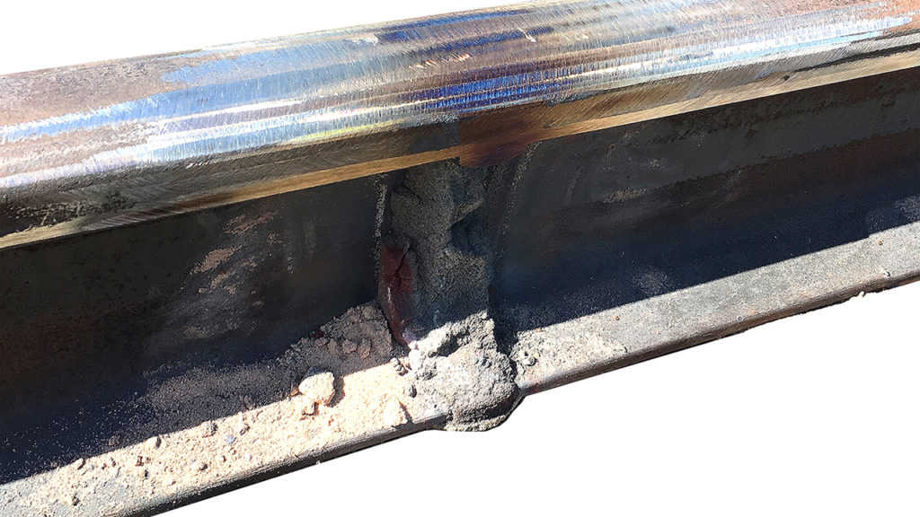
Regardless of the process used (thermite welding or flash welding), the completed rail joint must be dressed using grinders to ensure a proper running surface and gage surface for train wheels. Figure 4 is a photograph of a completed and dressed thermite rail weld.
In summary, welded rail provides a continuous and smooth rail head that allows wheels to cross rail joints without impacts. Impact-free rail joints minimize the stresses imposed on the rails and wheels, which helps ensure the long-term safety, reliability and efficiency of overall rail operations.
We would love to hear from you! Let us know about any railway engineering and technology questions and topics that you would like us to cover in future Timeout for Tech articles. Send us an e-mail at [email protected].

Dr. Fry is the Vice President of Fry Technical Services, Inc. (https://www.frytechservices.com/). He has 30 years of experience in research and consulting on the fatigue and fracture behavior of structural metals and weldments. His research results have been incorporated into international codes of practice used in the design of structural components and systems, including structural welds, railway and highway bridges, and high-rise commercial buildings in seismic risk zones. He has extensive experience performing in situ testing of railway bridges under live loading of trains, including high-speed passenger trains and heavy-axle-load freight trains. His research, publications, and consulting have advanced the state of the art in structural health monitoring and structural impairment detection.