Timeout for Tech: Ties and Ballast Time-Tested Foundation
Written by Gary T. Fry, Vice President, Fry Technical Services, Inc.; Railway Age Contributing Editor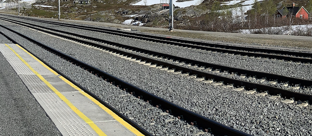
Figure 1. Rail, ties, and ballast on a heavy-haul mountain railway above the Artic Circle in Norway. (Courtesy of Gary T. Fry.)
RAILWAY AGE, NOVEMBER 2023 ISSUE: Both are essential for a rugged, lasting railway.
Welcome to “Timeout for Tech with Gary T. Fry, Ph.D., P.E.” Each month, we examine a technology topic about which professionals in the railway industry have asked to learn more. This month our subject is ties and ballast.
The basic concept for a railway is hard steel wheels rolling on hard steel rails—the most efficient form of ground transportation for heavy loads ever conceived and implemented. A basic question for a railway is how best to support the rails under the heavy concentrated forces of the moving wheels. A very effective answer comes in the form of a simple construction technique—ties confined within a consolidated layer of crushed rock, or ballast. Ties have been made successfully from a variety of materials: wood, concrete, steel, and even plastic. Ballast is generally made by crushing hard rock, such as granite or trap rock, into sharp-edged pieces ranging in size between 1 and 2 inches. Once placed and consolidated, such a ballast layer drains water very well (a critically important function) and is stiffly resistant to the tri-axial forces generated by heavy moving trains.
Using this type of construction, heavy-haul railways have been built and operated successfully through immensely varied terrain and weather conditions around the globe. For example, Figure 1 (above) shows rails, ties, and ballast on a heavy-haul railway above the Arctic Circle along a mountain grade in Norway. Figure 2 (below) shows rails, ties and ballast on a heavy-haul railway in the desert plains of the western United States. Despite the vastly different locations, terrains, climates and political jurisdictions, the railway tracks look more or less the same and utilize the same basic components: rails, ties, and ballast.
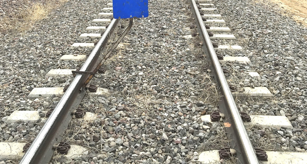
Figure 2. Rail, ties, and ballast on a heavy-haul railway in the desert plains of the western United States. (Courtesy of Gary T. Fry.)
Ties perform two main functions as part of the track structure: holding the rails to gauge (in essence, tying the rails together); and transferring tri-axial forces between the rails and the ballast—vertical forces, lateral forces and longitudinal forces. It is important to recognize in general that there is no ability for the ballast particles to “pull” on a tie. Therefore, forces transferred between tie and ballast rely on friction and also direct compressive contact pressure between tie surfaces and ballast particles.
We will begin by considering the transfer of vertical wheel forces and the manner in which vertical pressures vary among the contact surfaces down through the track structure. Load transfer through rails, ties, and ballast results in subgrade pressures under heavy rolling wheels that are comparable to a person walking on the ground. Let’s look at some estimates for the forces and pressures involved.
Figure 3 (below) is a drawing of the cross-section of a typical track structure showing the concentrated wheel loads, rails, tie plates, tie, ballast layer and subgrade (crowned to facilitate drainage below the ballast layer). Assuming a 36,000-pound wheel load, and a wheel-rail contact area of roughly 0.4 square inches, the estimated average vertical pressure between a wheel and a rail on the rail running surface is 90,000 PSI (pounds per square inch).
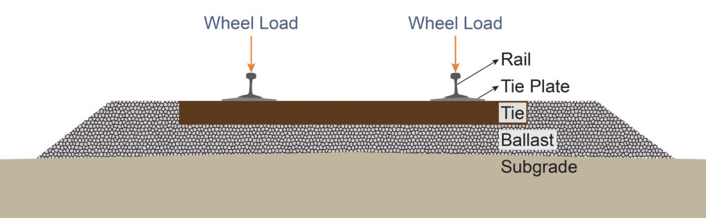
Figure 3. Schematic drawing of a track structure cross-section. (Courtesy of Gary T. Fry.)
Referring to Figures 1 and 2, we can imagine rails as beams that distribute a concentrated wheel load among several adjacent ties. For example, when a wheel is directly over a tie, we can estimate that the tie receives 50% of the load, with the rest being shared among the tie’s four nearest neighbors—two on either side.
Using this 50% estimate, the maximum force at the base of the rail, at a tie directly below the wheel, is close to 18,000 pounds. Given a basic area of contact between the base of the rail and a tie plate of roughly 45 square inches, the estimated average vertical pressure at the base of a rail is 400 PSI. Given a basic area of contact between a tie-plate and a timber tie of roughly 110 square inches, the estimated average vertical pressure between the plate and the tie is 170 PSI. Given an area of contact between one-half of a timber tie and the ballast of roughly 460 square inches, the estimated average vertical pressure between the tie and the ballast is 40 PSI. Finally, at the base of the ballast layer, under the center of the tie, measured average pressures between the ballast and subgrade have been reported as low as 5 PSI under 36,000-pound wheels—nearly 20,000 times smaller than the pressure between wheel and rail at the rail’s running surface.
Now we consider lateral forces. Ties and ballast hold the rails in alignment as the rails guide heavy trains through even the sharpest curves. In its function as a guideway, rail depends upon strategic geometric detailing that ensures favorable interaction between wheelsets and rails, especially in curves. Notably, the rolling surfaces, or treads, of wheels are not flat edge to edge. The treads are conical with their radius increasing between the edge of the rim and the face of the flange. The conicity of their treads gives wheelsets an ability to self-center when rolling along straight (tangent) track and an ability to steer themselves around curves. Moreover, the shape, or profile, of the railhead is designed to maintain favorable contact conditions with the wheelsets when the rail deforms laterally under wheelset steering forces. At times there are very large forces trying to push the rails apart and move the track sideways, but the tie and ballast system provides the required restraint.
The lateral forces from rolling wheels are transferred into a tie by its connection to the rail through the tie plate fasteners and through friction between the base of the tie plate and the surface of the tie. In turn, the lateral forces in the tie are transferred into the ballast through frictional contact with the ballast particles directly under the tie. Some lateral force transfer can also occur through compressive contact pressure between tie surfaces and ballast, especially at the end of the tie where the force is resisted by the ballast shoulder.
Finally, we consider longitudinal forces. Ties and ballast are essential elements of the longitudinal force load path making it possible for trains to stop and go. Generally, the significant longitudinal forces in rails arise from the various traction forces applied by locomotive wheels (for example, acceleration, braking, and tractive effort against train resistance and uphill grades) and the braking forces applied by rolling stock wheels.
Ties receive longitudinal forces from rails in three ways: connection to rails through tie plate fasteners—especially when elastic fasteners are used; friction between the tie plates and the ties; and through the use of rail anchors that are attached to the base of rail on both sides of a tie. Ties then transfer the longitudinal forces into the ballast through compressive contact pressure between the vertical faces of the ties and the ballast particles and also through frictional contact with the ballast particles directly under the tie.
This fundamental requirement to transfer longitudinal forces between rail and ballast comes with a drawback. Like most metal materials, rail steel expands when heated and contracts when cooled. Hence, when rail is subjected to temperature variations, it moves relative to the ground surface. But it cannot move freely because it is connected to ties that are confined in ballast. Significant longitudinal forces in rails are generated by these thermal effects—both compressive and tensile—especially in CWR (continuous welded rail). These thermal forces are strictly managed to mitigate the potential for damage to the track such as “sun kinks” in hot weather and “pull aparts” in cold weather.
From the discussion above, it is apparent that the interactions between ties and ballast are complex and involve nonlinear transfers of tri-axial forces—vertical, lateral and longitudinal. These force transfers cause incremental and cumulative tri-axial movements of the ballast particles relative to one another and of the ties relative to the ballast particles. As tonnage accumulates, periodic maintenance of the track is required to keep the rails within desired positional tolerances. Eventually wear and tear on the ties and ballast particles causes a need for replacement.
Ties and ballast are a time-tested, efficient, and effective foundation for a rugged and lasting railway.

Dr. Fry is Vice President of Fry Technical Services, Inc. (https://www.frytechservices.com/). He has 30 years of experience in research and consulting on the fatigue and fracture behavior of structural metals and weldments. His research results have been incorporated into international codes of practice used in the design of structural components and systems, including structural welds, railway and highway bridges, and high-rise commercial buildings in seismic risk zones. He has extensive experience performing in-situ testing of railway bridges under live loading of trains, including high-speed passenger trains and heavy-axle-load freight trains. His research, publication, and consulting have advanced the state of the art in structural health monitoring and structural impairment detection.