Siemens unveils first Amtrak Cities Sprinter locomotive
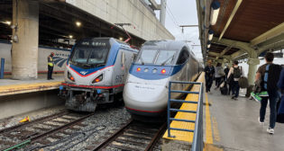
Written by Douglas John BowenAmtrak said early May 13 the first of 70 ACS-64 (Amtrak Cities Sprinter, 6.4 MW/8,320 hp) electric locomotives for the Northeast Corridor rolled off the Siemens Mobility assembly line in Sacramento, Calif.
The first units of the $466 million order will be field tested this summer for entry into revenue service on the NEC this fall, augmenting, and eventually replacing, elderly AEM-7 units that have protected NEC service for decades, and that have average mileage of more than 3.5 million miles traveled, with some approaching 4.5 million miles.
Three locomotives will undergo a comprehensive testing program this summer, including two in Pueblo, Colo., at TTCI, and one on the NEC. Production of the remaining units will occur through 2016.
 “The new Amtrak locomotives will help power the economic future of the Northeast region, provide more reliable and efficient service for passengers, and support the rebirth of rail manufacturing in America,” said Amtrak President and CEO Joseph Boardman. “Built on the West Coast for service in the Northeast with suppliers from many states, businesses and workers from across the country are helping to modernize the locomotive fleet of America’s Railroad.”
Components for the ACS-64s were supplied by Siemens plants in Norwood, Ohio, Alpharetta, Ga., and Richland, Miss., as well as from 70 suppliers, representing more than 60 cities and 23 states, Amtrak said.
The new locomotives will handle Northeast Regional trains at speeds up to 125 mph on the NEC, and also up to 110 mph on Keystone Service trains between Philadelphia and Harrisburg, Pa. Long-distance trains operating on the NEC also will be powered by the new locomotives.
“More and more Americans are parking their cars and choosing the comfort and convenience of trains, metros, and streetcars as their preferred way of traveling. We’re proud of the innovations we’ve brought to passengers and commuters to expand their transportation options,” said Michael Cahill, President of Siemens Rail Systems division in the U.S.
The ACS-64 is designed for easier maintenance, and will improve energy efficiency by using a regenerative braking system that will feed energy back into the power grid. The locomotive also meets the latest federal rail safety regulations. “We are committed to connecting people, communities, and jobs. This project does all three,” said Deputy Federal Railroad Administrator Karen Hedlund.
CLICK HERE To see a video of the ACS-64 rollout at the Siemens Mobility plant in Sacramento
TECHNICAL SPECIFICATIONS (as published in the June 2011 issue of Railway Age)
The ACS-64 offers high efficiency, reduced life cycle cost, and better reliability and availability than Amtrak’s existing electrics. In terms of traction capability with the maximum specified trainload, the ACS-64 can accelerate 18 Amfleet coaches with a Head End Power (HEP) load of 1,000kW to 125 mph in just over eight minutes.
The ACS-64 is an integral monocoque wide-body, double-cab design suited for push-pull operation. The carbody is comprised of four major elements—underframe, sidewalls, operator cabs, and three detachable roof sections. It is designed to allow compression forces of 800,000 pounds of buff load and is equipped with an AAR F-type coupler with a push back mechanism to achieve full anticlimber engagement.
Instead of a “conventional” mechanical safety concept in accordance with American Crash Standard AAR S-580 with collision and corner posts, the ACS-64 features a front end Crash Energy Management (CEM) system that provides better safety to crews while offering the advantage of lower weight and better reparability.
The ACS-64 has a center walk-through engine room. More space is available for components, maintenance access is much better, and component thermal effects are minimized, enabling better ventilation. This is the standard engine room layout for the Siemens European EuroSprinter and Vectron locomotives, and most of the electrical components are identical.
Since Amtrak’s NEC has three different a.c. catenary voltages, the ACS-64 is designed for 25kV 60Hz, 12.5 kV 60 Hz, and 12 kV 25Hz. A rotary switch in the converter connects the transformer windings for the required configuration. The traction control system consists of two cubicles located in the center of the locomotive on both sides of the walk-through, each containing components for one two-axle truck as well as the HEP supply.
Each converter cubicle has two water cooled input inverters (four-quadrant choppers) and three water cooled output inverters with IGBT power semiconductors. The two input inverters feed one common d.c. link for the three output inverters in one cubicle. Two of these output inverters are connected to the two a.c. traction motors of one truck in a single-axle control configuration, and one output inverter provides the redundant feed for the HEP and locomotive auxiliary systems.
Traction and locomotive control is performed by the Siemens SIBAS® 32 control system. The core of the control system is the Multi-Vehicle-Bus (MVB), interfacing with the subsystem control computers, all the I/O stations, as well as the Man-Machine Interfaces such as controls and displays on the engineer’s console.
The ACS-64 contains a 100% redundant HEP and AUX inverter system. It can operate at full speed at 100% traction power with one failed HEP inverter, or with a potential delay with one or two traction inverter or traction motor failures. System-critical components such as traction motors, inverters, and control system components are derived from service-proven systems.
Regenerative braking up to 100% rated power is possible, depending on the actual receptiveness of the grid. Main line electric locomotives typically spend approximately 8% of operational time in electrical brake mode, and given today’s average electrical energy cost, this, combined with highly efficient electrical components, can add up to considerable energy savings.
Each identical operator’s cab is equipped with three interchangeable 10-inch displays. A primary and a secondary screen are mounted in front of the operator and one in front of the assistant. They are equipped with hard keys for dedicated-, explicit screen-, and customer-specific soft functions. The primary display shows momentary operational information such as speeds, tractive and brake effort, and brake system pressures, while the secondary screen displays system diagnostic data, messages, and warnings. Screen redundancy is provided with the secondary screen taking over, if the primary display fails. The ergonomically designed operator’s console is an adaptation of the European Vectron design for North American requirements.