Commentary
Avoid Locomotive Jack Knife Derailments
Written by Michael Iden, P.E., Contributing Editor and Consultant, Tier 5 Locomotive LLC
RAILWAY AGE, SEPTEMBER 2023 ISSUE: At Railway Interchange 2023 in Indianapolis, there will be detailed presentations with Q&A of this topic (“Know Thy Couplers and Draft Gear”) for the International Association of Railway Operating Officers (IAROO) on Tuesday, Oct. 3 at 3:15 EDT, and the Locomotive Maintenance Officers Association (LMOA) on Wednesday, Oct. 4 at 9:30 EDT. Because this topic affects mechanical and transportation personnel, both organizations have supported the dual presentations. Discussion will also include industry recommendations.
North American railroads have significantly reduced the number and severity of derailments, especially since the Staggers Rail Act economically deregulated U.S. railroads in 1980. But while total derailments have declined, there continue to be a small number of “locomotive jack knife” derailments that can and should be eliminated; accomplishing that will take some decisions and actions.
Research shows at least nine such derailments in the U.S. and Canada in 1992, 1999, 2002, 2005, 2010, 2015, 2018, 2020 and 2023. One of the derailments destroyed a commuter locomotive in transit; another derailed 3 of 5 commuter locomotives; another damaged an unoccupied commuter platform; each damaged the older, shorter locomotives being transported plus freight cars; and one caused a hazmat spill (jet fuel). The 2023 derailment was investigated by the National Transportation Safety Board, and the derailments in 2002, 2005 and 2020 were thoroughly investigated by the Transportation Safety Board of Canada. All involved non-alignment control locomotives with “coupler stop blocks” instead.
The industry has several issues needing closure:
- There is no clear, concise and published industry-wide definition or standard as to what are alignment control couplers and draft gear. (An AAR Standard and definition would be best; we don’t need regulatory language.)
- The AAR-Railinc Umler file showing characteristics of registered locomotives has a field B008 that can be marked “yes” or “no” for “equipped with alignment control,” but there is no definition of what qualifies as a “yes.” (The two older units in the 2023 derailment were incorrectly coded as “yes” when they had “stop blocks.”)
- There is no uniform agreement between Class I’s, short lines and locomotive shippers regarding how non-alignment control locomotives can be safely moved.
Again, there don’t appear to be many such accidents, but they’ve happened across decades and they continue to happen—a warning flag. Will FRA accident reports provide details? Sometimes, but not always, because (as derailment investigation expert Gary Wolf has mentioned) the FRA Derailment Cause Codes tend to be “multiple choice”; FRA codes don’t include a specific “non-alignment control locomotive” code, and those who investigate derailments and decide on how to complete an FRA report may not be aware of this issue.
Before looking in detail at what are alignment control couplers and draft gear, let’s look at a typical derailment involving non-alignment control locomotives. What is a “locomotive jack knife” derailment and how do they typically occur?
These derailments typically involve one or more large, high-horsepower locomotives equipped with alignment control operating in dynamic braking, followed by one or more shorter locomotives, typically 4-axle commuter/passenger, road-switcher or switcher units, either working, isolated or shut down, and not equipped with alignment control couplers and draft gear. There is a freight train behind the non-alignment control locomotives.
The nine jack knife derailments I reviewed involved trains weighing between 4,512 and 17,201 trailing tons. Again, the key factors and the usual results: One or more short locomotives without alignment control couplers and draft gear, coupled behind larger units with alignment control in dynamic braking. The in-train forces were in “buff” (slack “in and bunched” against the locomotives), causing the non-alignment control couplers to “swing to the side,” squeezing the shorter non-alignment control locomotives into a jack knife orientation, causing a wheel climb or a rail rollover derailment.
Why don’t freight cars exhibit this jack-knifing tendency? Shorter locomotives tend to have greater distance from truck centers to coupler pins, creating unfavorable geometry.
Figure 1 gives a visual depiction (looking down from above) of what can happen when shorter locomotives not equipped with alignment control couplers and draft gear get into a “buff squeeze” between large locomotives in dynamic brake and the trailing tonnage of a freight train. We’re looking at a train moving right to left having 2 large units pulling (top) or in dynamic braking (bottom), with 2 short non-alignment control locomotives trailing, followed by the freight cars:
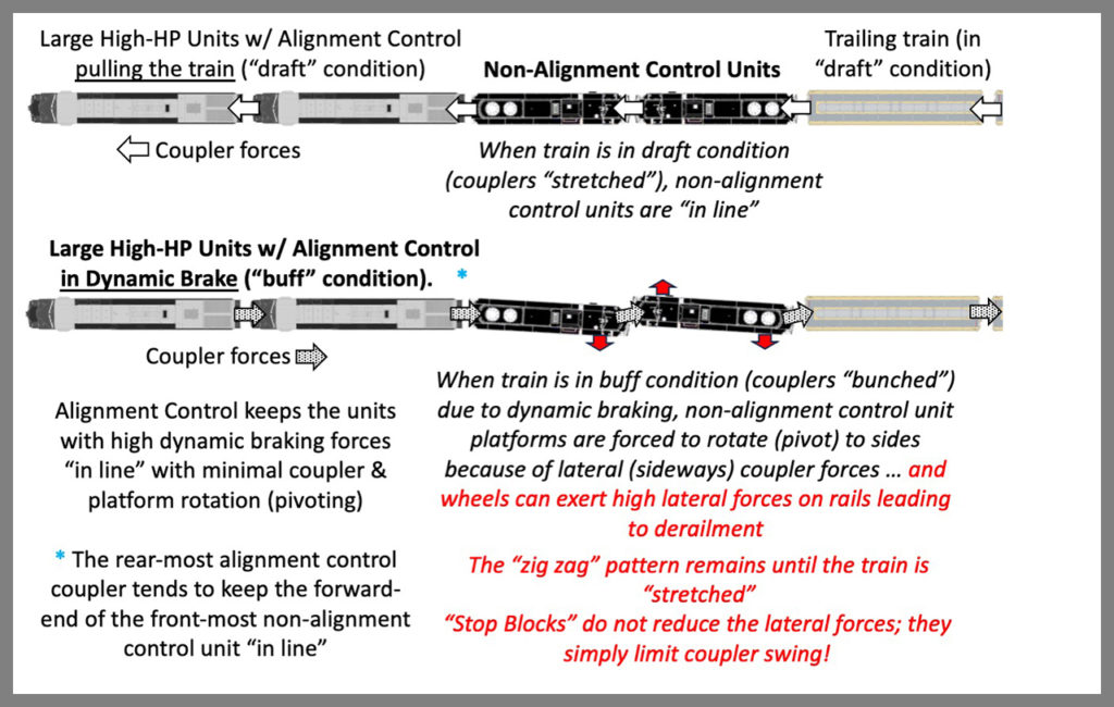
As the dynamic brake (retarding) force on the head end increases, the buff force acting from behind increases, and the non-alignment control couplers on the shorter locomotives begin to swing laterally (to the side). While the front coupler on the first short locomotive is generally kept in line by the rear alignment control coupler of the second dynamic brake unit, the other three couplers will gradually swing laterally (often “jamming” against one side of their coupler pocket) and the non-alignment control locomotives will assume the “zig zag” pattern shown. This is known as “yawing” (rotating around a vertical axis). The non-alignment control locomotives will maintain this orientation unless and until the train goes into a “draft” or couplers-stretched condition. Why is this a derailment risk?
When short locomotives without alignment control assume the “in buff and yawed” configuration, the lateral coupler forces transmit down through the locomotive underframe and trucks, causing the wheels to press against the rail head, and that can lead to (1) a flange climb derailment or (2) a rail rollover derailment. Ever heard about a “high L/V (lateral over vertical)” derailment?
All that said, what should be defined as “alignment control couplers and draft gear”? The answer can be found in U.S. patent 2,754,988 issued to William Metzger in 1956 (Figure 2) and assigned to a predecessor of the former National Castings. Expiration of the patent in 1973 has allowed several suppliers to produce and sell interchangeable alignment control couplers and draft gear for locomotives:
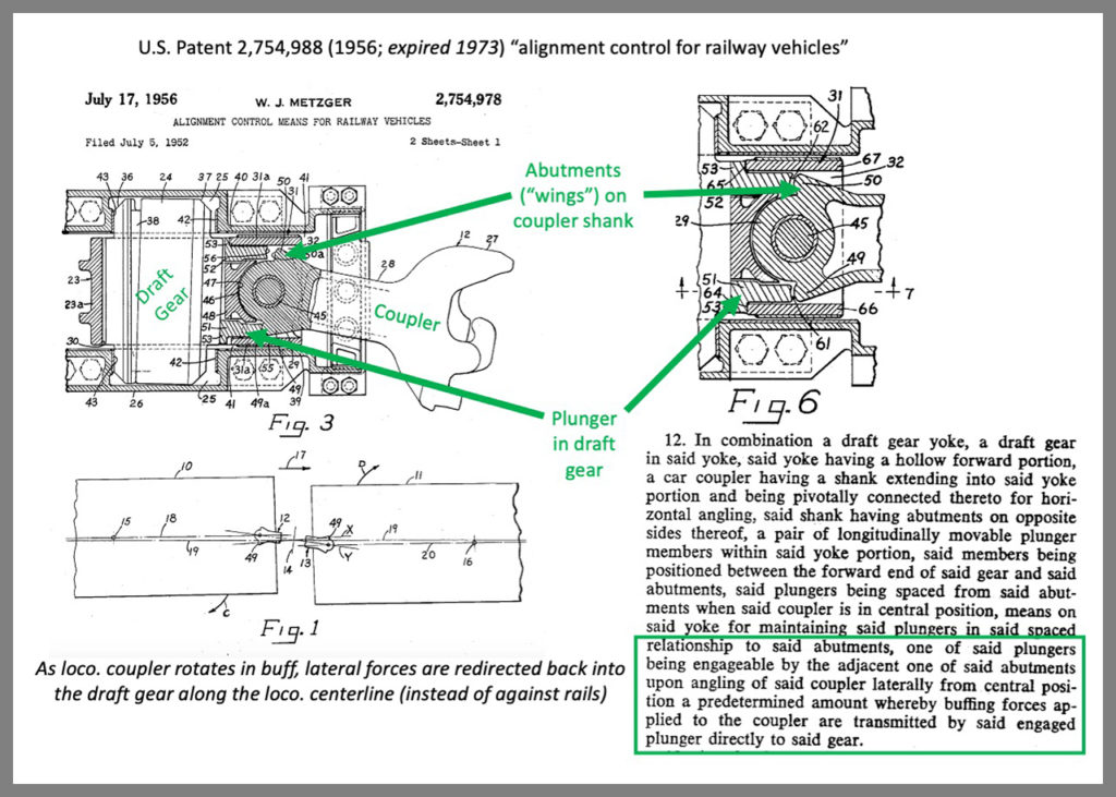
When the coupler rotates, an abutment or “wing” on the shank at the pin hole begins to press against a “plunger block” in the draft gear. As the draft gear is compressed (such as in dynamic braking), the draft gear resists the coupler’s rotation, limiting it to only 4 inches of swing to either side of the locomotive centerline. The coupler can never swing so far as to strike or come to rest against the sides of the coupler pocket. What would otherwise become a “side force” (coupler-to-coupler pocket) is redirected back into the draft gear parallel to the locomotive centerline. The AAR performed tests on the Rio Grande in 1954 verifying the reductions in coupler swing and lateral forces.
Figure 3 shows the two common types of freight locomotive couplers, type E (left) and type F (right). Type F is a “vertically interlocking” design (when 2 Fs are coupled) to better resist uncoupling in derailments. I have favored type F on high-horsepower locomotives since my management trainee days on Southern Railway (which used Type F couplers on all locomotives except switchers):
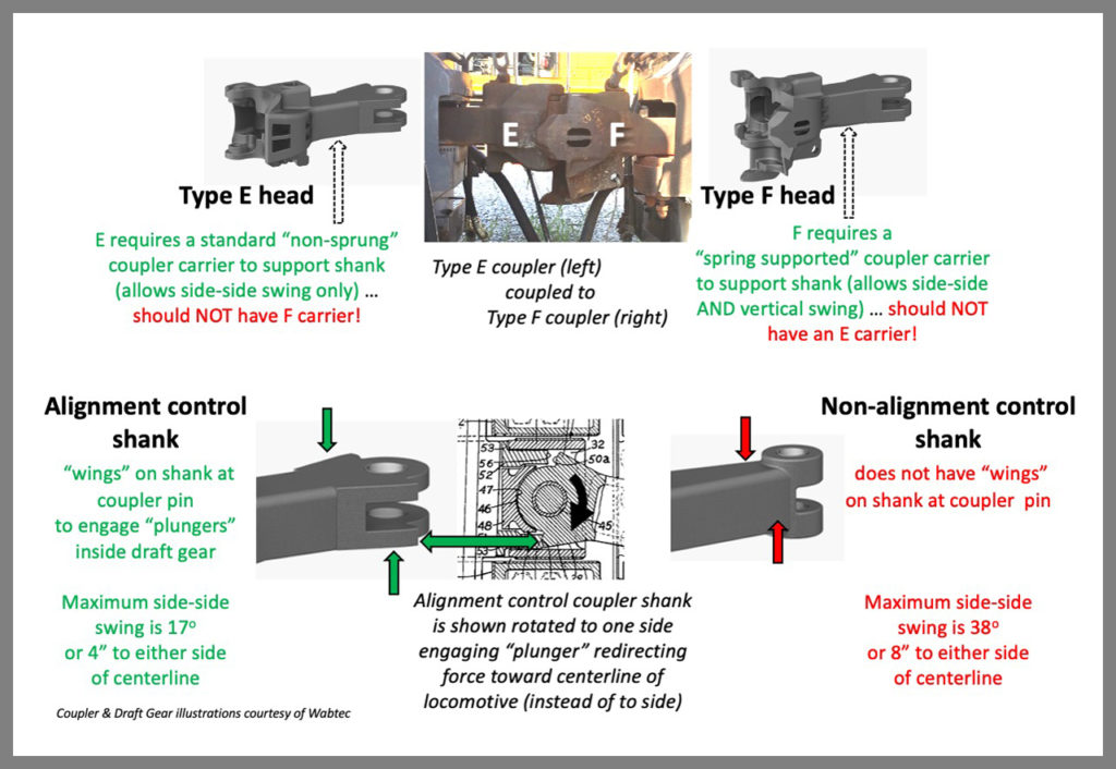
Figure 3 also shows the shank of an alignment control coupler (left) compared to a non-alignment control coupler (right). Note the “wings” on the alignment control shank, and look back to the patent drawing in Figure 2. My thanks to Wabtec for allowing me to use some of their coupler and draft gear illustrations.
Figure 4 shows an alignment control coupler about to be installed in an alignment control draft gear. If you are unsure if a locomotive has alignment control couplers and draft gear, the best verification is to safely move the coupler to either side of the locomotive centerline (using a coupler adjustment bar, for example). Alignment control limits coupler “swing” to only 4 inches to either side, and the shank should never contact the sides of the coupler pocket. Note that draft gear can accommodate E or F or E-only couplers:
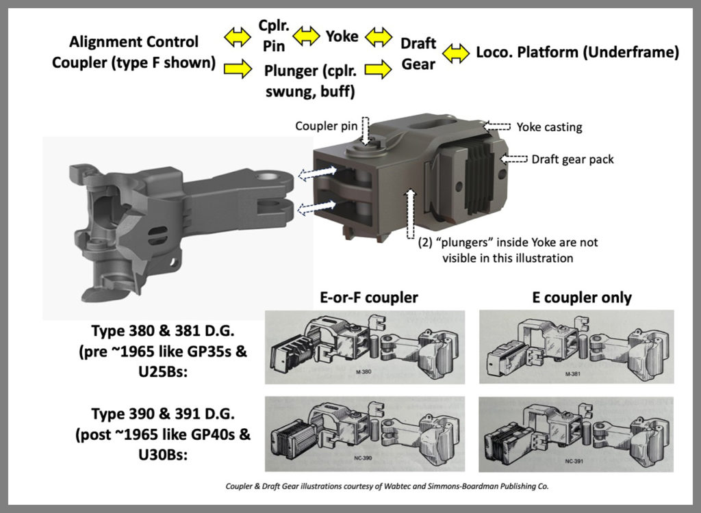
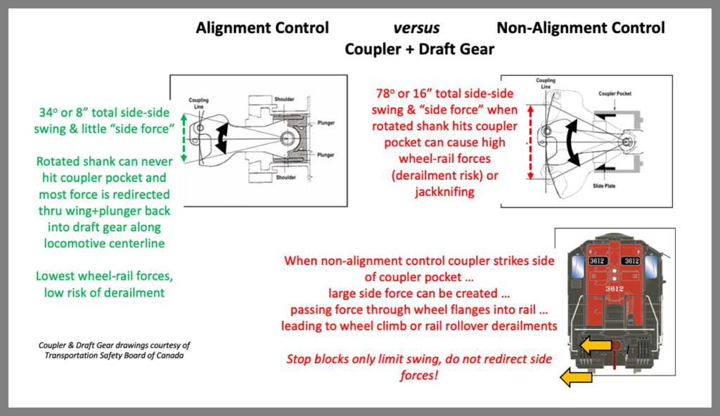
Figure 5 goes to the heart of what alignment control does. The left drawing shows a Type E alignment control coupler with an alignment control draft gear; note it can only swing 4 inches (or 17 degrees) to either side of the centerline. The right drawing shows a Type E non-alignment control coupler and a non-alignment control draft gear; note it can swing as much as 8 inches (or 34 degrees) to either side of the centerline, with the shank striking the coupler pocket at maximum swing. Both diagrams are in the three TSB reports from Canada (R02C0050, R05C0082 and R10T0056):
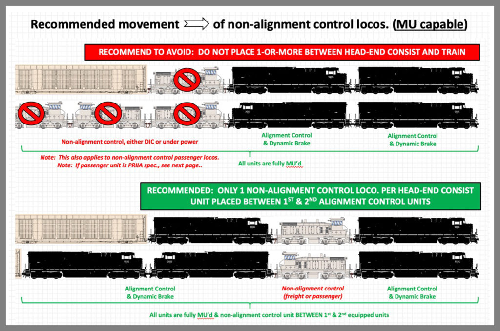
A problem for owners of older locomotives (such as GP9s and SW switchers) is they were manufactured without alignment control couplers and draft gear (which became common at EMD and GE for all high-horsepower units back around 1970; switchers were generally unequipped). You can have the locomotives modified, but retrofitting alignment control couplers and draft gear is a fairly expensive modification. Can such locomotives still be moved safely with non-alignment control? I believe it is possible, but railroad operating practice experts need to examine my suggestion in Figure 6. Hopefully, an industry best practice or uniform policy could be the result.
What I’m proposing, shown in Figure 6, is that only one non-alignment control locomotive be moved per train, coupled between two high-horsepower units equipped with alignment control (the bottom configuration), provided the older units have full multiple-unit capability. Putting any non-alignment control locos between the high-horsepower locomotives and the train (the top configuration) should always be avoided. If the older unit lacks multiple-unit capability, the only option would be to place it at the extreme rear end:
We will see what the AAR Locomotive and Operating Practices Committees decide.
Know Thy Couplers and Draft Gear!
Michael Iden is a registered professional engineer and locomotive and technology consultant (Tier 5 Locomotive LLC), having previously worked at the Southern Railway, GM Electro-Motive Division, C&NW and Union Pacific.