Mixed-traffic methods
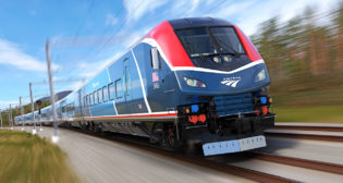
Written by AdministratorAs interest continues to build for high speed passenger operations, there is a significant potential for the addition of higher speed passenger trains to existing freight railroad lines.
The key advantage to this approach is that it allows for the introduction of higher speed passenger service with limited or no new track construction costs. This potential exists in what is commonly referred to as the “higher speed” (HrSR) passenger rail category, also referred to as the “emerging high speed” rail category, which can encompass current FRA Classes 5 and 6. While FRA Class 7 does allow the operation of special high performance freight equipment at speeds of up to 125 mph, it is usually not considered for mixed passenger/freight operations.
The lowest upgrade cost option is usually Class 5 track, which allows passenger train speeds up to 90 mph with conventional signaling systems. While Class 6 track allows operations at 90 to 110 mph, it does require upgrade of the signaling system to either Positive Train Control (PTC) or cab signals.
While no new track construction is usually required, upgrades to the track are often needed. These upgrades include improved track geometry, improved track superstructure (rails, ties, fasteners, etc.), and enhanced grade crossing protection. In addition, there is usually an increase in the ongoing track maintenance costs necessary to maintain track for mixed HrSR passenger and freight operations. This includes increased maintenance costs associated with maintaining the track to tighter track standards, curve unbalance issues, and increased inspection costs.
The issue of curve unbalance represents one of the key track design and maintenance issues for mixed passenger and freight operations. That is because high speed train operations are sensitive to curvature, with even moderate curves causing a significant impact on allowable operating speeds. Simply put, increasing curvature requires reduced speed operations in curves. In addition, there is a secondary effect associated with the need for train deceleration into the curves to achieve this reduced curve speed and the corresponding train acceleration out of the curves to get back to full running speed.
The actual speed limits for a given curve are subject to not just the curvature itself (usually defined in degrees of curvature or curve radius) but also to the elevation of the curve and the allowable unbalance or cant deficiency of the equipment. Elevation is the relative height of the outside rail over the inside rail on a curve, i.e. the “banking” of the curve. This is necessary so that the resultant force on the vehicle, as it goes through a curve, remains in the center of the track (as shown on p. 25). This resultant force is a combination of the downward acting vehicle weight (gravity force) and the speed-sensitive centrifugal force, which pushes the vehicle toward the outside of the curve.
The unbalance or “cant deficiency” is the amount of “overspeed” permitted for a given curvature and elevation combination. It is usually defined in terms of inches of unbalance (or millimeters of cant deficiency) and is a function of vehicle design, vehicle-track dynamic behavior, and allowable levels of safety. Traditionally, 3 inches (75 mm) is the North American standard for most railway operations, as used in the FRA Track Safety Standards. This is the maximum unbalance allowed for freight equipment, though up to 4 inches (100 mm) of unbalance is allowed for “qualified equipment,” usually passenger equipment with improved suspension systems. In addition, for Class 6 and higher track, increased unbalance may be allowed based on special high performance equipment. However, this requires specific FRA approval for each class of equipment and is primarily aimed at sophisticated passenger equipment such as tilting trains or other designs that compensate for the high centrifugal forces.
Since unbalance is usually limited to 3 or 4 inches by FRA standards, increased elevation is necessary to allow for increased operating speed, particularly passenger train speeds. Noting however that the maximum elevation is likewise limited to 7 inches (175 mm), there is a well defined maximum allowable speed for any given degree of curvature. This is critical in a mixed passenger and freight train environment, because the lower speed freight trains operating on a track with a large elevation will have their resultant force shifted to the inside (low side) of the curve. When the resultant force shifts too far to the inside of the curve, the car can overturn.
Even if the car does not overturn, the vertical forces from the slow but heavy freight cars will cause increased track damage due to this shifting of weight on high elevation curves. This includes “crushing” or “flattening” of the low rail due to the weight shift to the low rail, wear and damage to the gauge corner of the high rail due to reduced curving performance of convention freight cars, as well as increased tie damage and increased degradation of the track geometry, particularly surface and cross-level.
This curvature effect on speed is illustrated in Table 1 (p. 27), which shows the maximum allowable speed by curvature for track with 6, 4, and 3 inches of elevation respectively. Note, these values are based on 4 inches of unbalance, which is allowed for improved-performance passenger equipment.
As can be seen from this table, for curves of 3 degrees, the maximum passenger train speed is 69 mph with 6 inches of elevation and 60 mph with 3 inches of elevation, which is a more appropriate amount of elevation if there is a significant amount of freight traffic on that curve. For curves of 4 degrees, this speed drops to 50 mph with 3 inches of elevation, and to 41 mph on a 6 degree curve. On a 12 degree curve, it would drop further to 29 mph. Again, that the greater the elevation, the more track damage that will be experienced from the freight traffic and the greater the risk of a car overturning, particularly if the freight train has to reduce its speed or stop on the curve.
If the passenger equipment had to operate with 3 inches of unbalance on a heavy freight line with 3 inches of elevation to reduce track damage, then the allowable speeds would be as shown in Table 2 (p. 27) with a maximum speed of 40 mph on a moderate 5 degree curve and 27 mph on a severe 12 degree curve. Thus, even moderate curvature can result in significant speed reductions on mixed traffic track with maximum speeds of 40 mph to 50 mph and the associated deceleration and braking going into and coming out of these curves.
Track upgrade issues
Introducing higher speed passenger train operations on conventional freight track often requires upgrade of the track to higher standards with associated upgrade costs. These include upgrades to both FRA and railroad standards.
Among the areas of upgrade are grade crossings. For FRA Class 5 track with passenger train speeds up to 90 mph, conventional gates and flashers are sufficient. However for Class 6 track with 90 mph to 110 mph speeds, advanced grade crossing protection such as four quadrant gates or complete grade separation are required.
A second area of upgrade is the upgrade of the track structure itself. Aside from curve realignment costs, which can represent major capital upgrades, this can entail replacement of rails, ties, fasteners, turnouts, grade crossings, and other special trackwork. While rails and ties may be replaced based on condition of the existing components, high speed turnouts may be introduced to facilitate train operations through these traditional slow spots in the track. While No. 20 is the maximum turnout size usually seen on dedicated freight lines, higher speed passenger operations often see No. 24, No. 26, and even No. 30 turnouts to allow higher diverging speeds through the turnout.
Increased track geometry standards are directly associated with increased track class and higher operating speeds. As can be seen in Table 3 (p. 27), each level of upgraded track class has an associated tighter level of track geometry standards, which affects not only the initial upgrade of the track but also the ongoing track maintenance, with the need for more frequent track surfacing and alignment activities. This is particularly true for mixed passenger and freight operations, which have the issue of higher dynamic wheel/rail forces due to high speed operations, tighter track geometry standards, and high axle load freight operations operating at below balance speed. For example, a recent FRA study looked at the cost of maintaining mixed passenger and freight operations. It indicated that mixed passenger/freight lines can see a potential increase in maintenance costs of 40% to 70% or more.
Precision engineering for high speed tracks
By Plasser American, for Railway Age
Whenever line speed or capacity is increased or a new line is built, appropriate track maintenance and upgrading procedures are very important to enable optimal, efficient use. Investing in high-tech machines is paramount. Output of machines for track laying and maintenance is far greater than before and intelligent control circuits are used increasingly. This directly affects work results and cost-effective project performance. The focus should be on the long-term effect of a maintenance operations and optimization of costs.
Track defects of different wavelengths stimulate carbodies with different frequencies. Frequencies between 0.5 and 10 Hz are considered critical for rolling stock. At lower speeds, these frequencies are caused by short wavelength errors, so correcting the track in a smoothing manner is sufficient. At higher speeds, defects in track geometry with larger wavelengths also cause considerable dynamic forces and therefore must be eliminated. Wavelengths of up to 330 feet (100 meters) must be considered at speeds of 100 mph; at 220 mph, even 660- foot-long (200 meter) defects cause rolling stock reactions. This theoretical survey coincides with the practical experience of high speed operators and caused a change in track maintenance strategies of some railways—changing from smoothing mode to absolute track geometry.
With the introduction of combined leveling-lining-tamping machines in 1960, the general trend was to perform smoothing track correction only. It quickly appeared that the tracks moved away from the original location, and transition points were shifted. Therefore, since 1972, fixed reference points were established on monuments or catenary masts in Austria and Germany. Track position is defined in relation to the fixed points and the versines in between; target values are saved in a general track database. France, Britain, Spain, and Italy also introduced similar systems on their high speed lines.
Before any precise track maintenance work is carried out, a track survey of the actual geometry, measuring the level and the alignment of the track, is done. In the past, extensive manual track survey with sighting instruments was involved. Today, the EM-SAT track survey car (above) enables fully mechanized measurement of the actual track geometry using a laser reference chord. Another solution is to equip tamping machines with inertial navigational measuring systems determining the deviations from absolute track position by a separate measuring run. The calculated correction values are transferred into the tamping machine’s Automatic Geometry Guidance System computer (AGGS). This guarantees highest precision and at the same time prevents any transmission faults that can occur in manual measuring.
Track maintenance requires a range of work processes that must be coordinated as efficiently as possible. The better work technologies interact, the higher the achievable work output, quality of work, and ultimately the cost efficiency will be. One of the latest machine concepts for high performance tamping machines is our 09-Dynamic. It incorporates a continuous action tie tamping unit paired with two stabilizing units on an integrated trailer. Especially on high speed lines, the 09-Dynamic is an interesting and cost effective alternative to the use of two or more separate machines. Due to increased overall performance, track possession time and consequently cost can be reduced.
Heavier designs of switches and crossings due to the use of concrete ties and heavy rail profiles demand additional measures for their treatment. When lifting such turnouts in the area of the long ties with the standard two-rail lifting unit, the reaction forces on the fastenings are already exceeding their yield strength. Therefore, an additional lifting arm for switch and crossing tamping machines was developed. This additional feature— the “3 S” type lifting—is a standard for today’s switch and crossing tamping machines. On most European railways, three-rail lifting on turnouts with concrete ties is mandatory.
Especially on high speed lines, it is important to create a minimum of transitions between different maintenance areas. It is therefore desired to have machines available that can maintain turnouts and tangent track in one process. To meet the demand of high accuracy and working speed, the continuous action principle is also applied in switch and crossing tamping machines. Such machines can also have integrated dynamic stabilization. We achieve our highest output with our 09-32 4S Dynamic continuous action tamping and stabilizing machine. Such machines are permanently positioned on high speed lines in Italy.
The continuous development and improvement of track maintenance machines has led to a series of designs for all applications that not only fulfil the high accuracy demands of high speed railroads but also provide cost effective solutions, either by increasing working speed as well as precision or by implementing technologies that save precious raw materials.
New high-tech machines contribute to the sustainability of investments in high capacity passenger lines as they enable to keep a high level of maintenance. Examples on European railways confirm that it is possible to build high speed lines on traditional tracks with long service life at low maintenance cost.


