
Timeout for Tech: Anthropomorphic Materials Characteristics – Stress, Strain, Strength, Fatigue, Toughness
Written by Gary T. Fry, Vice President, Fry Technical Services, Inc.; Railway Age Contributing Editor
Figure 1. From “The Spirit of Transportation,” an 1895 bas-relief by Karl Bitters displayed in Philadelphia’s 30th Street Station. In engineering, it is common to use terms associated with the human experience to describe characteristics of materials—stress, strain, strength, fatigue and toughness. (Courtesy of Gary T. Fry.)
RAILWAY AGE, MARCH 2023 ISSUE: Welcome to “Timeout for Tech with Gary T. Fry, Ph.D., P.E.” Each month, we examine a technology topic that professionals in the railway industry have asked to learn more about. This month, our subject is properties of engineering materials.
Figure 1 (above) is a photograph of a portion of an 1895 bas-relief by Karl Bitters displayed in Philadelphia’s 30th Street Station: “The Spirit of Transportation.” There are several interesting connections between the work of artists and the work of engineers. For example, artists use materials to represent aspects of the human experience; engineers use the human experience to represent aspects of materials—stress, strain, strength, fatigue and toughness, to name a few. I am often asked about the engineering meanings of these terms.
Let’s start with stress and strain. Figure 2 shows drawings of a beam that is supported by blocks at each end. In Figure 2-a, the beam is not loaded. In Figure 2-b, the beam bends under a load applied at its center, and its supports also deform. The bend in the beam and deformation of its supports are measurable on a global scale. Less obvious is what happens inside the materials used to make the beam and its supports—internal forces and internal deformations. One should imagine these two effects occurring at the atomic scale; atomic lattices of materials deform as interatomic bonds work to resist these internal forces. This is generally where the engineering concepts of stress and strain apply—within materials at an infinitesimal scale. Consequently, stress and strain are termed differential quantities.

Specifically, stress is the term we use to describe the intensities of internal forces that are distributed throughout materials under load. Stress has units of pressure, for example pounds per square inch (psi). Strain is the term we use to describe the intensities of internal deformations that are distributed throughout materials under load. Strain is mathematically (but not conceptually) dimensionless with units of deformation over length, for example inches per inch (in./in.). The state of stress at a given point in a material is represented as a 3×3 symmetric matrix of values called a tensor. The state of strain at a material point is also a 3×3 symmetric tensor. Stress and strain occur together and are related to one another through material-specific functions called constitutive equations. (Hooke’s Law is an example of a simple constitutive equation, and its uniaxial expression is familiar to most engineers.)
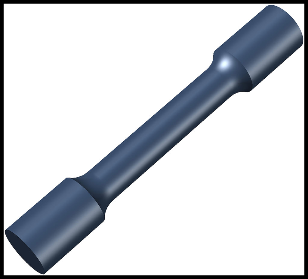
We are now ready to introduce the concept of material strength. The strength of a material is usually defined simply as the maximum stress that can be applied to the material before the material fails. Therefore, strength has the same units as stress—for example, psi. To establish its strength, controlled tests are performed on samples of a material. Figure 3 is a drawing of a standard “tensile test” specimen used to establish the strength of ductile metals. The specimen is usually five inches long and half an inch in diameter along its midsection. In this test, the ends of the specimen are gripped and pulled by a machine until the specimen breaks in two. The load applied to the specimen and the elongation of the specimen are recorded continuously during the test. After the test is complete, the load and elongation data sets are used to calculate the strength of the material.
The concepts of stress and strength work hand in hand and are essential to ensuring the safety of our built environment. In designing and evaluating a component for safe use, engineers rely on calculations of stresses in the component and specifications for the strengths of the materials that comprise the component. The objective is for the strengths of the materials to exceed the stresses in the materials by reliably and statistically significant margins.
Here it is worth noting that given the fundamental concept of stress (and, by association, strength), it is only possible to determine stresses and strengths through calculations using mathematical models of materials and components. It is never possible to measure stresses in any material by any means either directly or indirectly. During my early studies in solid mechanics, I was told quite emphatically by an eminent scholar that anyone who claims that stress can be measured “is at best ignorant but more likely incompetent and a threat to safety.”
Despite the facts of the situation, the internet is full of references to means of “measuring stress” in engineering materials. One must take care interpreting these claims. There is a field called experimental stress analysis, and I frequently evaluate components in service using its tenets. The work involves attaching sensors—oftentimes strain gages—to existing components and subjecting them to loadings consistent with their intended service. The data sets from the sensors feed into models of the components and their constituent materials.
Using those models, and data from the sensors, estimates for the component stresses can be calculated. All else being equal, however, different models can lead to substantially different calculated stresses, even when using the same sensor data as input. In situations involving high levels of stress, such as wheel/rail contact, the stress calculations can be very complex involving iterative nonlinear computer algorithms and multiscale material models.
In summary, stresses in materials can only be estimated using mathematical models, and the calculations may or may not incorporate sensor data from components under load. Regardless, the act of incorporating sensor data with a calculation of stress does not transform the result into a measurement of stress. Claiming otherwise is a misrepresentation with potential safety and/or economic implications.
Our next term is fatigue. Fatigue is defined generally as the process that leads to the formation of cracks (or other defects) in sound material after the application of many cycles of loading. When stresses at a certain magnitude or higher are applied to steel, natural atomic-scale imperfections move, or glide, until they reach a surface—for example the peripheries of metallurgical discontinuities or of the members themselves. There they cease movement, but the geometry of the atomic lattice has now changed permanently. Atomically sharp steps are formed at the free surfaces, and the process is not reversible. With the repeated application of stresses, such as wheels rolling over a rail, more dislocations move, and more sharp steps are formed. With the accumulation of more stress cycles, the iron crystals eventually separate at the steps forming fatigue cracks. As more stress cycles are applied, the fatigue cracks grow, potentially leading to complete fracture of a component.
Our last term is toughness. Toughness is a measure of a material’s resistance to allowing a crack to grow longer under the application of stress. It has units of energy per unit area of crack formed. All solid materials have toughness. The toughness of metals usually varies with temperature: generally lower at cold temperatures and higher at warm temperatures.
Figure 4 is a photograph of a test specimen used to establish toughness values for steel. The specimen includes a sharp, machined notch. The test is conducted in two stages. First, the specimen is subjected to a cyclic load to initiate and grow a fatigue crack from the notch. Then, the specimen is subjected to an increasing load until the specimen fractures. Several specimens from a given material are tested at different temperatures to establish the sensitivity of the material to cracks over its expected range of operating temperatures. Data sets recorded during each test are used to calculate a quantity called Fracture Toughness, which is directly related to Material Toughness but reflects the relationship among Material Toughness, applied stress and fatigue crack size.

In general, the larger the value of Fracture Toughness, the larger the fatigue crack that can be tolerated before triggering a fracture. Hence, higher fracture toughness gives us a better chance of detecting the crack before it causes failure. It is worth noting here that a crack tolerated on a warm summer day, when the Fracture Toughness is high, might well trigger a brittle fracture on a cold winter day, when the Fracture Toughness is low. The only difference being the value of Fracture Toughness in the material; the crack size and stress level remain identical. Inspection protocols must take this temperature dependence into account to be fully effective.
Stress, strain, strength, fatigue and toughness are familiar concepts in the daily lives of people all over the world. But these words take on special meaning as essential properties of structural materials. Each has a critical influence on the safety and reliability of every engineered system in our built environment.

Dr. Fry is the Vice President of Fry Technical Services, Inc. (https://www.frytechservices.com/). He has 30 years of experience in research and consulting on the fatigue and fracture behavior of structural metals and weldments. His research results have been incorporated into international codes of practice used in the design of structural components and systems including structural welds, railway and highway bridges, and high-rise commercial buildings in seismic risk zones. He has extensive experience performing in situ testing of railway bridges under live loading of trains, including high-speed passenger trains and heavy-axle-load freight trains. His research, publications, and consulting have advanced the state of the art in structural health monitoring and structural impairment detection.