
Ultrasonic Testing of Steel
Written by Gary T. Fry, Vice President, Fry Technical Services, Inc.; Railway Age Contributing Editor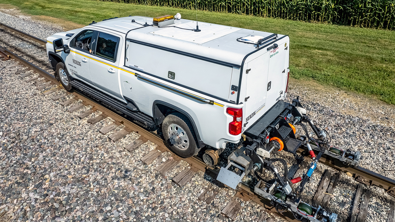
Figure 4A: Ultrasonic testing equipment customized for rail inspection. Courtesy of Herzog.
RAILWAY AGE MARCH 2022 ISSUE: Welcome to “Timeout for Tech with Gary T. Fry, Ph.D., P.E.” Each month, we examine a technology topic that professionals in the railway industry have asked to learn more about. This month, our topic is fatigue defect detection in steel.
Fatigue defects are a common cause of failure of steel components that resist dynamic loads. For this reason, fitness for service assessments of such components nearly always include specific inspections that are designed to detect the presence of fatigue defects. Unfortunately, detecting the defects can be quite difficult. This is primarily because fatigue cracks are usually exceptionally thin, having measurable length and width but negligible thickness. As a result, even when a large fatigue defect extends from the surface of a component, it might be apparent only as a very thin, faint line that is not easily seen with the unaided eye—very easily missed.
Sometimes fatigue defects do not extend to the surface of the component, remaining completely encased within. Such defects are termed internal defects or subsurface defects and are essentially invisible. This is common with fatigue defects in railway wheel rims and rail heads. For example, Figure 1 (below) illustrates a typical transverse fatigue defect in a rail head. The defect is tinted in green and is located near, but a bit below, the top surface of the rail. The important question is this: How can such defects be detected? One way to do this is with acoustic wave energy.
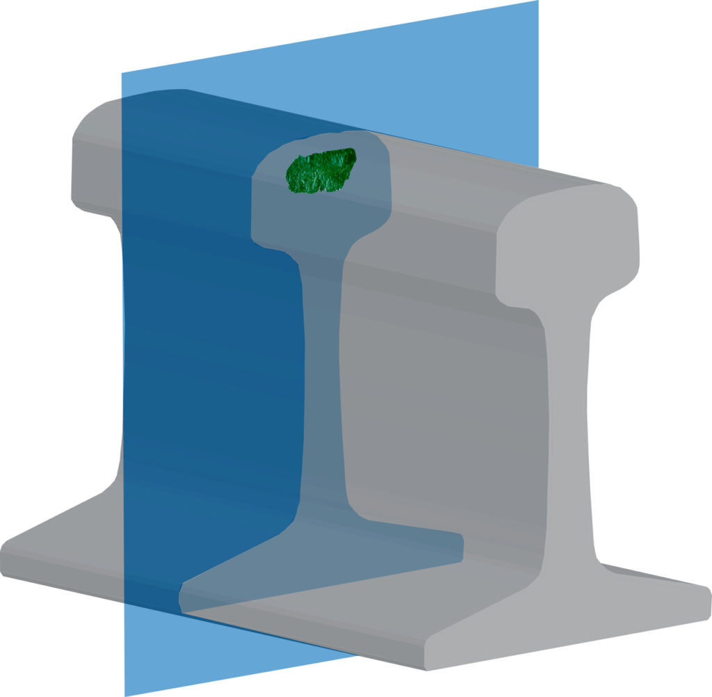
Figure 1: Schematic illustration of a rail head fatigue crack. Commonly, cracks in rail heads and wheel rims are completely contained and invisible.
Figure 2 (below) is a photograph of a gondola floating through a Venetian canal on a quiet summer afternoon. As the boat glides along, the bow of the boat and the gondolier’s oar generate small waves. If we look closely at the magenta square inset in the photograph, we can see that some of those waves are reflected back into the canal after encountering the wall of a building.

Wave motion is the underlying principle of technology that allows us to create images of internal body structures in medical examinations and to “see” invisible fatigue defects inside solid steel. It is also how some animals, in complete darkness, can locate and capture food while avoiding obstacles, competitors and predators. The technology is called ultrasound, ultrasonic non-destructive testing (NDT), ultrasonic testing (UT) or echolocation.
As the name implies, ultrasonic testing involves high-frequency sound energy. Specifically, ultrasonic means beyond human hearing. The frequencies used in ultrasonic inspection are usually in a range centered around 5 million Hertz. This is true for medical applications as well as inspection of steel. For comparison, the highest frequency sound detectable by a sensitive human ear is roughly 20,000 Hertz.
There are four terms to define that will help us understand the basic features of ultrasonic testing. To do this, we will again refer to Figure 2. The gondola is a wave generator. The water in the canal is the wave propagation medium. The building walls are wave reflectors. And you, the reader examining the photograph, might be viewed as the wave detector. Those are the four basic terms to keep in mind—all to do with waves: generation, propagation, reflection and detection.
With these basic terms in place, we can describe how ultrasonic testing works. Waves of high-frequency sound energy are generated and introduced to a propagation medium. If the propagating waves encounter an obstacle—a discontinuity in the propagation medium such as a fatigue defect—reflective waves are created. When reflected waves are detected, that is a direct indication of the presence of a discontinuity within the propagation medium.
For example, the echolocation capabilities of animals such as bats and dolphins might be considered a form of ultrasonic testing. The animals generate clicks at frequencies around 100,000 Hertz—that is, waves of ultrasonic sound energy. For bats, the propagation medium is air; for dolphins, it’s water. They are then able to detect reflected waves and visualize the objects that caused the reflections—apparently quite accurately, since bats can detect and capture mosquitoes this way.
In our example, the propagation medium is a steel rail that might have an internal fatigue defect. As the waves propagate in the steel, if a defect is present, it will act as a reflector sending reflected waves in a new direction compared with the original waves. At a basic level, the waves reflected from the defect can be detected and used simply to indicate the presence of the defect. In full-featured applications, the reflected waves can also be used to create refined, three-dimensional visual images of the defect and quantify its location, size, shape and orientation. Perhaps as ultrasonic testing’s most refined example, scanning acoustic microscopy (SAM) can be used to create three-dimensional images of very small objects and the defects that they contain.
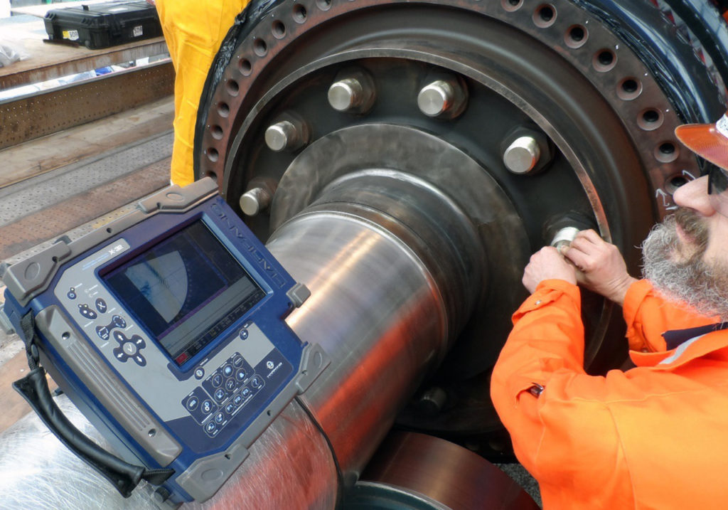
Ultrasonic testing has widespread application in fitness for service assessments of engineered systems. Figure 3 (below) is a photograph of a technician using phased array ultrasonic testing to inspect the threads of long bolts that secure a combustion turbine. As seen in the photograph, the technician only needs access to one end of each bolt to perform the complete inspection.
Figures 4A (lead photo, top) and 4B (below) are photographs of ultrasonic testing technology customized for the inspection of rail: A) equipment (Herzog Series 7000 Duramax) mounted for in-motion inspection of rail; B) a technician interpreting data on a display.

Fatigue defects can be very difficult to detect, especially when they are completely internal to a component. Today, owners have access to ultrasonic testing technology to non-destructively inspect their critical components and systems. In railway applications, rails are inspected routinely using ultrasonic testing. In this way, fatigue defects internal to the rail head can be detected and removed. Wheel rims are subjected to similar dynamic contact loads as rails and also develop internal fatigue defects. Ultrasonic testing can be used effectively to detect those defects in wheels.
Ultrasonic testing allows us to create images of invisible defects using inaudible sound energy. It is a technology truly inspired by Nature.

Dr. Gary Fry is Vice President of Fry Technical Services, Inc. He has 30 years of experience in research and consulting on the fatigue and fracture behavior of structural metals and weldments. His research results have been incorporated into international codes of practice used in the design of structural components and systems, including structural welds, railway and highway bridges, and high-rise commercial buildings in seismic risk zones. He has extensive experience performing in situ testing of railway bridges under live loading of trains, including high-speed passenger trains and heavy-axle-load freight trains. His research, publications and consulting have advanced the state of the art in structural health monitoring and structural impairment detection.