Guideway, Bearing, and Beam: The Essential Roles of Rail
Written by Gary T. Fry, Vice President, Fry Technical Services, Inc.; Railway Age Contributing Editor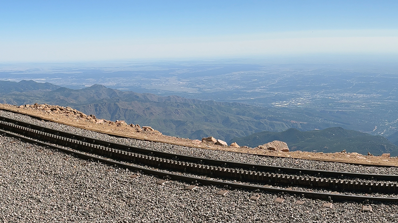
FIGURE 1. Track of the Broadmoor Manitou and Pikes Peak Cog Railway. Reaching 14,115 feet at the summit of Pikes Peak, it is the highest railway in North America and the highest cog railway in the world. (Courtesy of Gary T. Fry.)
TIMEOUT FOR TECH, RAILWAY AGE NOVEMBER 2022 ISSUE: The mass movement of goods and people by rail is the second-most energy efficient mode of transportation—second only to watercraft in navigable waterways. A main contributing factor to the efficiency of rail transportation is the extremely low rolling resistance created by hard steel wheels rolling on hard steel rails. Another factor is the favorable aerodynamic slipstream created by trains at speed.
There are no theoretical limits as to the maximum weight or maximum length of a train. But there are practical limits that arise from economic, social, political, technological, geographic, geologic, and topographic constraints, all of which must be managed effectively for a railway to be successful. Regardless of these constraints, however, in terms of energy efficiency, rail transportation enjoys substantial and fundamental scientific advantages over every other transportation mode in existence, except waterborne transportation. The trick is to have a railway where you’d like it to be.
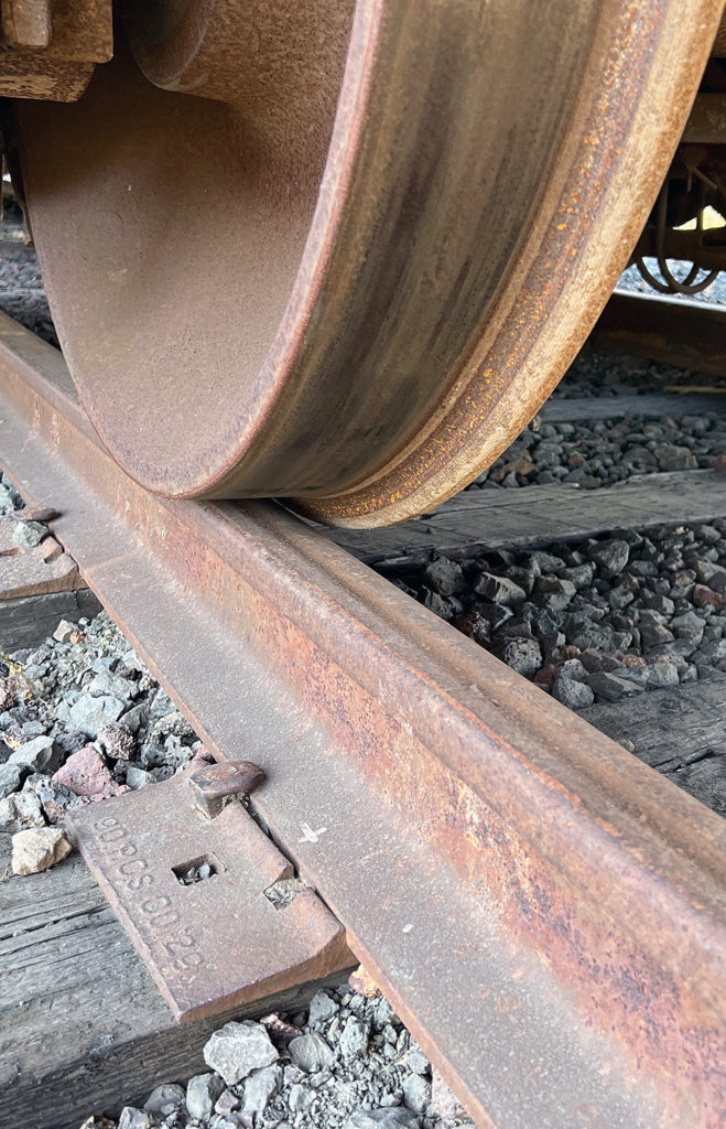
FIGURE 2. Closeup view of a rail and wheel in contact. Although formed from a single piece of steel, rail serves three purposes simultaneously: as a guideway, as a bearing, and as a beam. (Courtesy of Gary T. Fry.)
Fortunately, railways are economically efficient and competitive to build, and they can be built almost anywhere. Figure 1 (above) shows an extreme example: the Broadmoor Manitou and Pikes Peak Cog Railway. Originally built more than 130 years ago, this railway climbs 7,800 feet in elevation along nine miles of track to reach the summit of Pikes Peak at 14,115 feet. Let’s take a closer look at the essential feature of this and every railway: the steel rail.
The steel rail of a railway serves the roles of three components at once: guideway, bearing, and beam. We’ll consider each of these in turn. Figure 2 (left) is a closeup view of a rail and wheel in contact. First, the inside edge, or gauge face, of the rail serves as the ultimate, or final, guiding surface that restrains excessive lateral movement of wheel flanges, thereby keeping wheelsets properly on top of the rails. Second, the top surface of the rail is the linear bearing upon which heavily loaded wheels roll. Finally, the rail serves as a beam that distributes the wheel loads onto the crossties so that the weight of moving trains can be supported by the underlying layers of the track foundation.
In its function as a guideway, the rail depends upon strategic geometric conditions that ensure favorable interaction between wheelsets and rails, especially in curves. Notably, the rolling surfaces, or treads, of wheels are not flat edge to edge. The treads are conical with their radius increasing between the edge of the rim and the face of the flange.
The conicity of their treads gives wheelsets an ability to self-center when rolling along straight (tangent) track and an ability to steer themselves around curves. Moreover, the shape, or profile, of the railhead is designed to maintain favorable contact conditions with the wheelsets even as the rail deforms laterally under wheelset steering forces.
With exposure to wheel forces, the rail top surface and gauge face (inside edge) will experience wear that changes the railhead profile. Similarly, the treads and flanges of wheelsets experience changes to their profiles because of wear. Measurements of railhead profiles and wheel profiles are collected periodically and compared against target profiles. When necessary, rails are ground with abrasive disks and wheels are machined to maintain their profiles for favorable dynamic interaction during train movements.
Next, we consider the rail acting as a bearing. On a heavy axle load railway in North America, the forces on a single freight car wheel can be as high as 36,000 pounds. Where the wheel and rail contact, the steel deforms—in much the same way that your fingertips flatten when you press them together. Because of the deformation in the wheel and rail, the 36,000-pound force is distributed over an area roughly the size of a dime, or a little smaller. This tiny patch of contact from a large force is one reason that the rolling resistance of trains is so small, which is very desirable.
There is a consequence, however, to having large forces acting over small areas. Engineers often refer to force distributed over an area using the term stress. Stress is a representation of the intensity of a force as it acts on a material—the larger the stress, the more demand on the material. Large forces on small areas create large stresses and require strong materials. Therefore, steel is used as a material of choice for wheels and rails. Specifically, among other attributes, steel alloys are chosen that are economical to produce in large volumes and that can be processed to be strong, resistant to forming fatigue defects, and resistant to abrasion and wear.
Stress can be analyzed in a component using a variety of techniques, including computer modeling, and can be visualized using plots of color gradients (fringe plots). For example, Figure 3 (below) is a fringe plot of stress distributions within a wheel and rail at the center of their contact patch. The stresses were calculated using a computer modeling technique called finite element analysis (FEA). In the head of a railroad rail, within the wheel-rail contact patch, contact stresses are maximal and can cause damage, such as wear, to occur on the wheel and rail surfaces. Just below the running surface in the rail, the stress levels are lower but often high enough to cause damage in the form of fatigue defects. Stress analysis is a powerful tool that is used to design not only components but also the materials systems from which components are made.
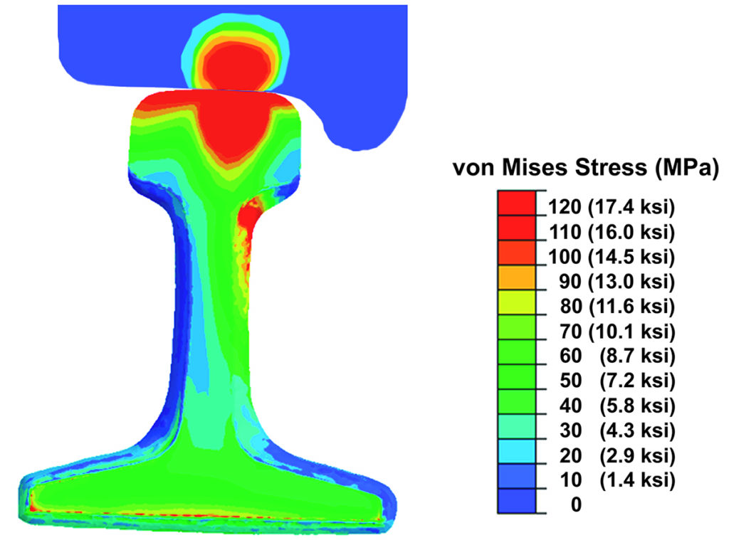
FIGURE 3. Fringe plot of stress distributions in a wheel and rail at the edge of a thermite rail weld. (Courtesy of Gary T. Fry and Maryam Tavakoli.)
Finally, we consider rail acting as a beam. The wheel loads are applied to the tops of the rails. The rails are supported at intervals along their length by crossties under their bases. The crossties, in turn, are supported by the rocky ballast layer of the trackbed. Because of the spacing between the crossties and the compressibility of the ballast layer, the rail flexes vertically under the wheelsets as they roll along. Here the geometry of the rail is a main feature to consider, in addition to the strength of the steel alloy used. Specifically, the area of the railhead, the area of the rail base, and the rail height are optimized. The objective is for the rail to flex within safe limits and for the wheel loads to be spread among several ties at a time so that the trackbed, and natural soil beneath, can support the weight of passing trains. A larger railhead or rail base or a taller rail would all lead to less flexural deformation but would also require more steel making the rail more expensive. Hence, the rail shape is optimized to provide acceptably safe and reliable performance at the least cost.
Steel rail is the essential component that establishes railway transportation as uniquely efficient energetically and economically. Railways can be built almost anywhere to support the operation of trains of great weight, great length, and great speed and they can take us to awe-inspiring vistas in nearly every corner of the world. All of this is made possible by the rails acting concurrently as guideways, bearings, and beams.

Dr. Fry is the Vice President of Fry Technical Services, Inc. He has 30 years of experience in research and consulting on the fatigue and fracture behavior of structural metals and weldments. His research results have been incorporated into international codes of practice used in the design of structural components and systems, including structural welds, railway and highway bridges, and high-rise commercial buildings in seismic risk zones. He has extensive experience performing in situ testing of railway bridges under live loading of trains, including high-speed passenger trains and heavy-axle-load freight trains. His research, publications, and consulting have advanced the state-of-the-art in structural health monitoring and structural impairment detection.