Metal Fracture: The Fatigue Cycle That Really Counts
Written by Gary T. Fry, Vice President, Fry Technical Services, Inc.; Railway Age Contributing Editor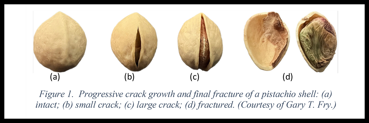
FIGURE 1
RAILWAY AGE FEBRUARY 2022 ISSUE: Welcome to “Timeout for Tech with Gary T. Fry, Ph.D., P.E.” Each month, we examine a technology topic that professionals in the railway industry have asked to learn more about. This month our topic is fracture of steel.
Welcome to “Timeout for Tech with Gary T. Fry, Ph.D., P.E.” Each month, we examine a technology topic that professionals in the railway industry have asked to learn more about. This month our topic is fracture of steel.
I am often asked, “Why did this break?” Typically, the inquirer is pointing to a piece of steel that has suffered an obvious fracture. Structural fractures can occur even when a component is only subjected to the normal service loading that it was designed to withstand with a significant margin of safety. In fact, the component may have supported millions of applications of the loading for many years before the fracture suddenly occurred. So what was special about that last load application that caused the fracture? The simple answer is, probably nothing special at all. A more vexing answer might be this. The last load did not cause the fracture; it was the fracture which resulted in that becoming the last load.
Let’s consider generally what comprises a fracture event using a broadly familiar object: a pistachio. Figure 1 (above) contains a sequence of four photographs of pistachio shells: intact, slightly cracked, very cracked, and fractured. This sequence is representative of how steel components might fail in fatigue. They start off intact, develop small fatigue cracks which grow into larger fatigue cracks, and then fracture.
If offered one of the first three pistachios, I would certainly choose the one that contains a larger crack, since little force is needed to pry it open. In general, the larger the crack, the easier it is to fracture a solid, and we should always distinguish between a crack and a fracture. A crack is a defect in a component; a fracture is a failure of a component, often into two or more separate pieces.
There are fascinating microscopic things happening inside solid material at the tip of a crack just prior to a fracture event. These things comprise the fracture process and are best represented mathematically as a tipping point in a balance among three energies. In the context of opening the pistachio shell these energies are: 1) the energy created as the forces in our fingers spread apart; 2) the strain energy inside the solid shell caused by our fingers prying the shell open; and 3) the energy required to extend the length of the crack within the solid shell material.
That third energy, the energy required to extend the crack, involves a material property that we call Toughness, (also referred to as critical strain energy release rate). It has units of energy per unit area of crack formed. All solid materials have toughness. The toughness of metals usually varies with temperature: generally lower at cold temperatures and higher at warm temperatures. Here are some toughness values of a few materials at room temperature. For our pistachio shells, it is around 10,000 Joules per square meter. For glass, it is very low: around 10 Joules per square meter. For copper, it is very high: around 1,000,000 Joules per square meter. For the low-carbon steels used in bridges and buildings, it is around 100,000 Joules per square meter. For the hard, wear-resistant pearlitic steels used in railroad rail and railcar wheels, the toughness is around 10,000 Joules per square meter, surprisingly similar to pistachio shells.
With that introduction, let’s focus on the engineering principles that are used to mitigate brittle fracture failure of steel components. Up to now, I have assumed the existence of a crack defect in the material as a precursor to fracture—and with good reason. Steel components without crack-like defects rarely experience brittle fracture under normal loading. Rather than being limited by Toughness, their performance is limited by their inherent uncracked strength, which is a different engineering material property.
For example, every broken railcar wheel rim that I have examined triggered from a fatigue crack defect—usually substantially larger than one inch in dimension. In some cases, multiple large fatigue crack defects were involved in the wheel failure—so-called multiple site damage (MSD) scenarios. With very rare exception, the broken railroad rails that I have examined also triggered from fatigue crack defects—usually in the head or base.
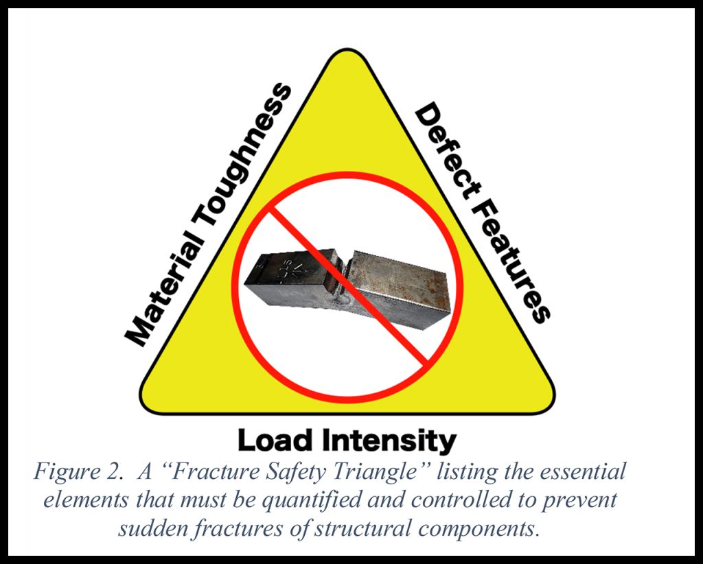
The energy balance described for the pistachio example provides valuable insight to the problem. Material toughness, fatigue crack size, and load level are independent variables. For a given material toughness and some level of applied load, there is a critical sized fatigue crack that will trigger a brittle fracture. Alternatively, given a material toughness and a fatigue crack of some size, there is a critical level of applied load that will trigger a brittle fracture. Finally, given a fatigue crack of some size and an applied load of some level, there is a critical material toughness that will trigger a brittle fracture. Figure 2 is a diagram that represents these essential considerations (toughness, defect, and load) imagined as a fracture safety triangle.
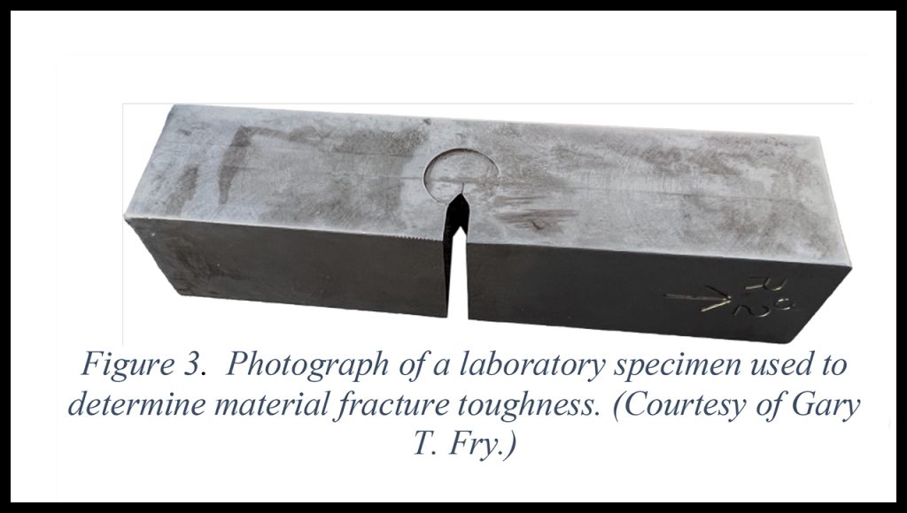
Better understanding of the engineering properties associated with these types of fractures comes from laboratory tests using fatigue-cracked specimens. Figure 3 is a photograph of a test specimen used to establish toughness values for steel. The specimen includes a sharp, machined notch. The test is conducted in two stages. First, the specimen is subjected to a cyclic load to initiate and grow a fatigue crack from the notch. Then the specimen is subjected to an increasing load until the specimen fractures, similar to prying open a pistachio shell. Several specimens from a given material are tested at different temperatures.
Data sets recorded during each test are used to calculate a quantity called Fracture Toughness. Fracture Toughness is directly related to Material Toughness but reflects more directly the criticality relationship among Material Toughness, applied load intensity, and fatigue crack size.
Figure 4 is a plot of Fracture Toughness versus Temperature for pearlitic steels used in railroad rail and railcar wheels. As was indicated earlier, the Fracture Toughness varies with temperature, being lower at cold temperatures and higher at warm temperatures. The ranges of expected Fracture Toughness values are indicated by blue shading on the plot—substantial variability is observed.
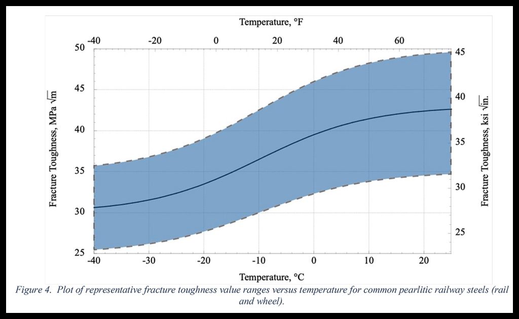
In general, the larger the value of Fracture Toughness, the larger the fatigue crack that can be tolerated before triggering a fracture. It is worth noting here that a crack tolerated on a warm summer day, when the Fracture Toughness is high, might well trigger a brittle fracture on a cold winter day, when the Fracture Toughness is low. The only difference being the value of Fracture Toughness in the material; the crack and loading remaining identical.
Considering the fracture safety triangle, Figure 2, as it relates to some of the details of freight rail transportation in North America, there are some practical constraints to note regarding Load Intensity and Material Toughness. The loads in North American freight rail transportation are not arbitrary. They are limited to maximum levels according to published equipment interchange rules and are carefully controlled to be permissible in revenue service. In addition, as reflected by the plot in Figure 4, the Fracture Toughness of rail and wheel steel is rangebound but substantially temperature dependent. That leaves fatigue crack size and temperature as the only variables that are not controlled.
Regarding fracture of steel rails and wheels, here are the key takeaways. Though controlled, the loads imposed on wheels and rails in North America’s heavy-haul freight rail system are sufficient to cause fatigue crack defects. On rails, fatigue cycles accumulate with the passages of loaded wheels. On wheels, a fatigue cycle accumulates with each revolution under load.
Furthermore, at potentially varying rates, fatigue cracks grow during all seasons of operation: summer, fall, winter, and spring. Even after millions of cycles of load successfully applied, left unchecked, there can be a fatigue crack that grows to be critical under a single additional cycle of load applied at a given temperature (really at a given Fracture Toughness), triggering a fracture.
One can reasonably expect to see clusters of these fractures with the arrivals of the coldest days of winter. The fractures are triggered by cracks that survived the coldest days of the previous winter, though perhaps barely so. These cracks continued to grow but managed to remain subcritical through the warmer spring, summer, and fall days but were now critical in the cold. If they had been this size the previous winter, they would have triggered fractures then.
The most effective countermeasures are to regularly inspect for cracks in rails and wheels and remove the defective components from service.

Dr. Gary Fry is the Vice President of Fry Technical Services, Inc. He has 30 years of experience in research and consulting on the fatigue and fracture behavior of structural metals and weldments. His research results have been incorporated into international codes of practice used in the design of structural components and systems including structural welds, railway and highway bridges, and high-rise commercial buildings in seismic risk zones. He has extensive experience performing in situ testing of railway bridges under live loading of trains, including high-speed passenger trains and heavy-axle-load freight trains. His research, publications, and consulting have advanced the state of the art in structural health monitoring and structural impairment detection.