FRA PTL: Supporting Next-Generation Train Operations
Written by Sam Alibrahim, Chief, Train Control and Communication Research Division, Federal Railroad Administration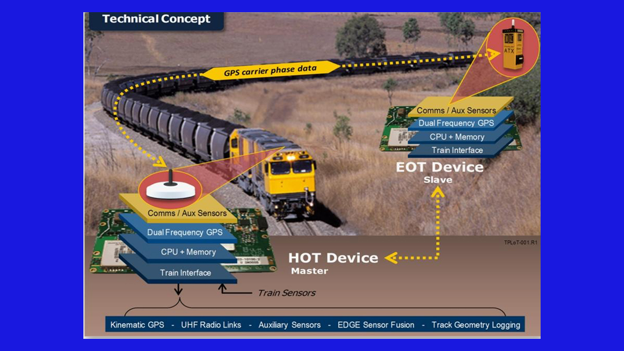
The ability to precisely locate and track train movement on the rail network is the cornerstone of modern train control systems. The Interoperable Electronic Train Management System (I-ETMS) and Positive Train Control (PTC) systems currently used by Class I railroads, operational on approximately 54,000 route-miles, rely on the Global Positioning System (GPS) to identify the location of the train lead locomotive, crew-entered track information, and switch position. The location of the rear of the train is then derived from the location of the lead locomotive using the train length, typically provided by the railroad’s management information systems (MIS) and confirmed or updated by the locomotive engineer.
The relative inaccuracy of GPS and the manual entry of track information at train initialization often results in operational deficiencies. For these reasons, the Federal Railroad Administration (FRA) Office of Research, Development, and Technology (RD&T) and the railroads cooperatively launched research into innovative methods to precisely locate and track train movements. This research resulted in what is now known as the Positive Train Location (PTL) system, which is being commercialized by the railroad industry and deployed by Class I railroads.
PTL research was conducted in multiple phases from 2011 through 2017; in Phase I, FRA RD&T and the railroads set forth the following performance requirements:
- The PTL system is required to:
- Accurately determine the position of the locomotive.
- Accurately determine the position of the rear of the train.
- Accurately determine train location at initialization and during operation.
- Key performance requirements:
- Estimate navigation state for both Head-of-Train (HOT) and End-of-Train (EOT) units.
- Support HOT/EOT communications for trains up to 5 miles in length.
- Track HOT/EOT navigation state in all environments (with and without GPS).
- Support the following navigation accuracy requirements:
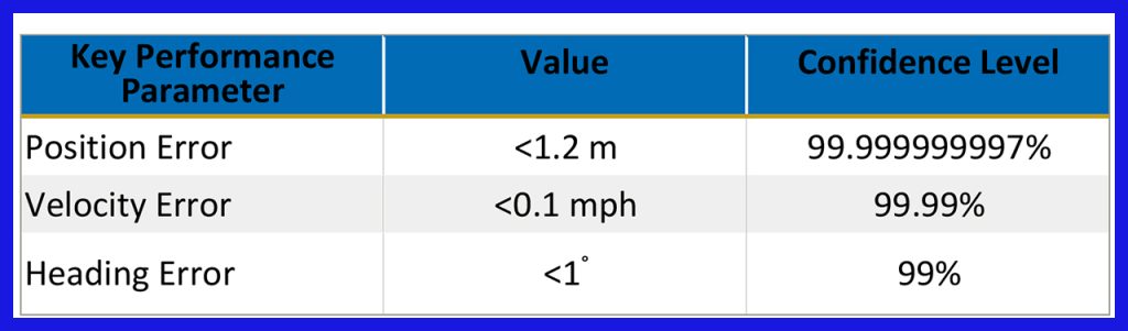
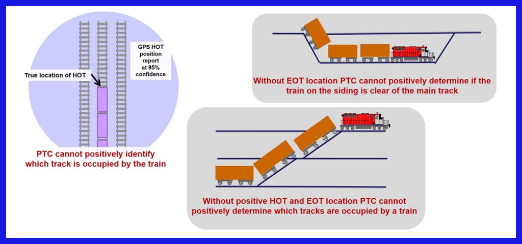
To meet these requirements, the PTL system must be capable of providing position measurements to an accuracy of <18 cm (1 σ, standard deviation) along-track and across-track standard deviation. With this level of accuracy, track discrimination capability as determined by across-track accuracy and along-track accuracy ensures that both HOT and EOT are safely secured within a siding to avoid fouling the main track. The figure below illustrates the impact of position uncertainty.
In addition, FRA RD&T and the railroads agreed on the requirement that positional accuracy must come without the aid of external infrastructure. This implies that the deployment of fixed “truth” reference Real-Time Kinetic (RTK) system base stations or subscription services may not be used. Consequently, positioning must be determined solely by an onboard Global Navigation Satellite System (GNSS) receiver, inertial navigation sensors, and software to support positioning when GNSS satellite visibility (including GPS) is degraded or unavailable.
Two qualified contractors, SAIC (now Leidos) and Boeing, competed to see which company could use integrated, commercial off-the-shelf manufacturer development kits to demonstrate potential accuracy and capability of the system that met or exceeded the performance requirements. Leidos won the competition and proceeded to develop a compact, ruggedized, commercial-ready system compliant with the American Association of Railroads (AAR) standard capable of integrating with the locomotive onboard computer and EOT. The system architecture includes a HOT segment located in the lead locomotive cab, an EOT segment integrated into the ETD, and a 900-MHz radio link between them in a master-slave arrangement.
The challenge for Leidos was how to design a low-cost system when available low-cost GPS receivers can only provide accuracy on the order of 200 cm (1 σ), and the most capable GNSS receivers without aid of an external reference or a satellite subscription service can only provide 30 cm standalone position accuracy. In addition, the MIS-provided train length is an approximation and not considered reliable enough by itself to determine the actual train length. Train length data should be dependable, as operating performance and safety can be affected when the PTC system is responsible for truncating or releasing movement authorities behind a train, for example, in dark territory. In addition, the current accuracy level of a GPS-based location used by PTC systems does not provide a sufficient level of accuracy to perform track-level discrimination under all conditions.
Leidos researchers had to take into account numerous sensor design considerations as they developed the PTL system. Additional sensors and sophisticated measurement filtering are necessary to reduce position error to within the 18-cm objective. These additional sensors include onboard locomotive devices such as a wheel speed sensor (WSS) and a gear selection signal to determine the direction of travel or stoppage, 3-axis accelerometers, gyros, and an altimeter. These sensors are optimally integrated through a process of sensor fusion that uses Leidos’ Embedded Data-fusion Geospatial Engine (EDGE). EDGE consists of a library of sensor fusion and filtering algorithms that may be generally applied to any set of sensors capable of providing position, velocity or heading (PVH) information. Comprehensive simulations were performed to identify a suite of sensors that could provide PTL accuracy requirements at minimal cost. Once the appropriate sensors had been selected and rigorously examined in test and operational environments, the resulting integrated hardware/software solution evolved to become the PTL system. Figure 2 illustrates the challenge and the requirements the PTL must meet to provide highly accurate and dependable PVH data.
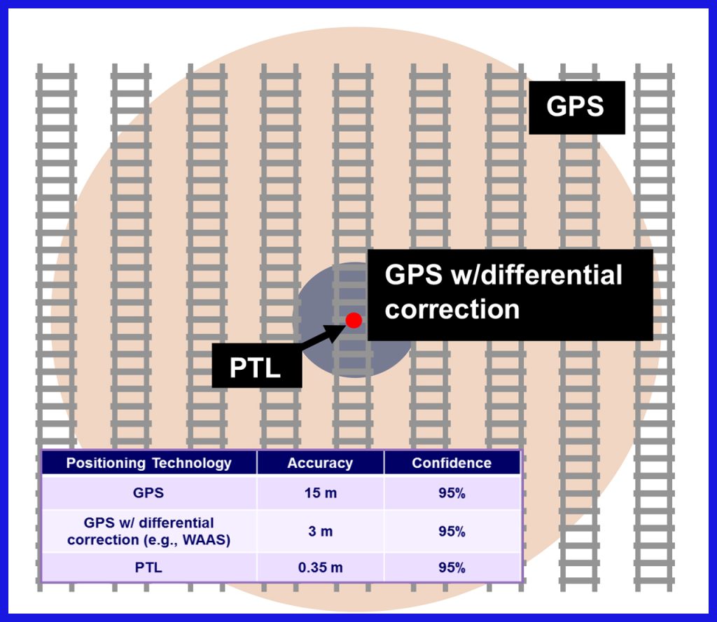
Figure 3 depicts the PTL high-level hardware architecture, consisting of the Catalyst TC processor module, Septentrio AsteRx-m GNSS receiver, Analog Devices ADIS16448 Inertial Measurement Unit, and Intuicom C1000µ 900-MHz radio.
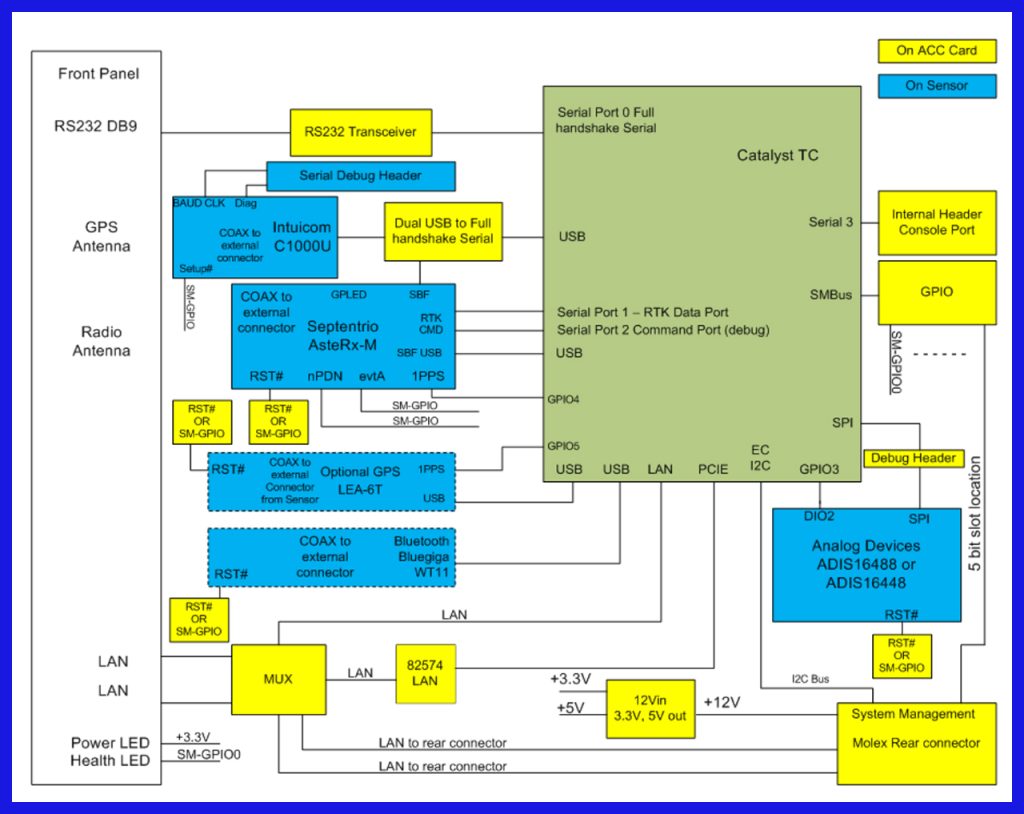
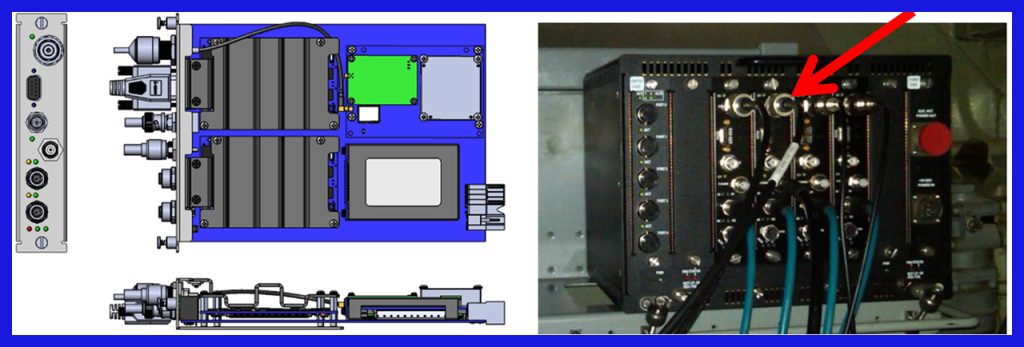
Figure 4 depicts the PTL HOT unit—an AAR Auxiliary Card Cage (ACC)-compliant circuit board. The PTL ACC card is operational in any ACC card slot and may be communicated with via the front panel Ethernet, backplane Ethernet, or RS232 front panel serial port. Front panel interfaces accommodate up to two M12-terminated Ethernet cables, one GNSS antenna cable (N-Male), and one 900-MHz antenna cable (RP TNC). Front panel LED lights indicate device operational state and health status.
While the PTL EOT unit maintains the same functionality as the PTL HOT, it employs a more compact form factor to accommodate ETD integration, as shown in Figure 5. Functionally, the only distinction between HOT and EOT is device configuration; the EOT is configured as a slave with respect to the HOT master. Consequently, the EOT employs its integrated 900-MHz radio to transmit its position information and RTK data to the HOT. The HOT then refines EOT position information by applying its stored past position history, a process Leidos calls “backward propagation.” The resulting HOT and EOT PVH data is then communicated to the train management computer (TMC) interface for PTC processing.
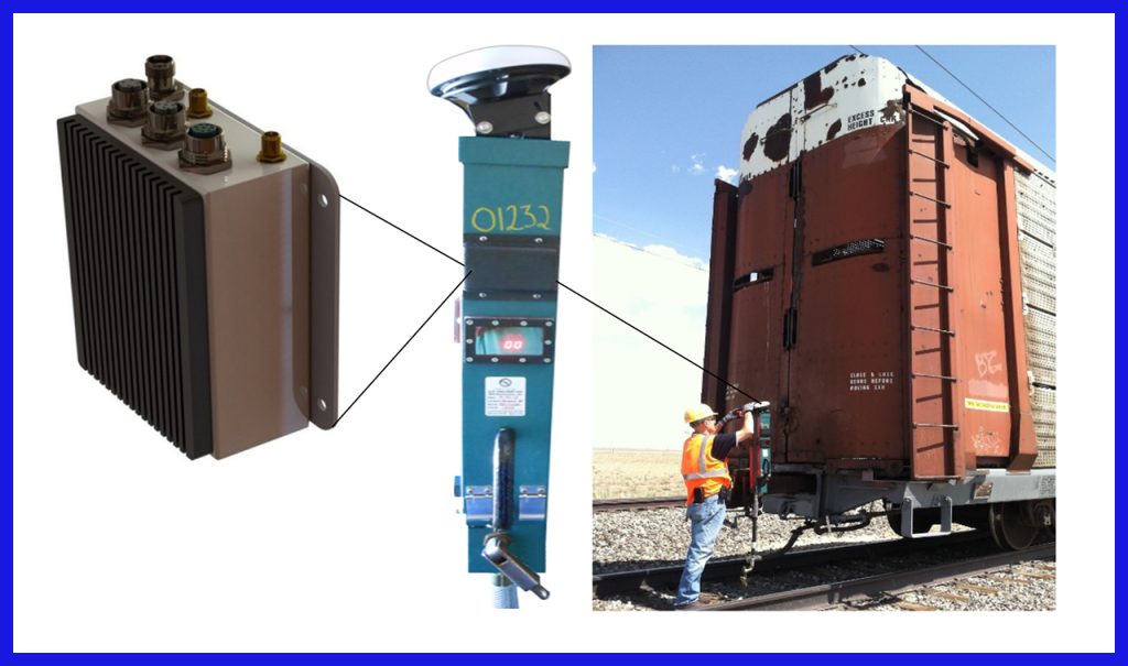
While integrated within an operational ETD, the PTL EOT unit does not interface with any ETD functions and only uses the ETD as a power source. The PTL HOT unit interfaces with a Wabtec WSS and locomotive gear selector through the Wabtec PTC TMC interface. PTL HOT input messages are sourced from the Wabtec Interoperable Electronic Train Management System (IETMS®) Locomotive 3000 series message data distribution.
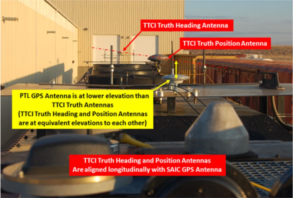
The PTL system went through rigorous testing at the Transportation Technology Center (TTC) in Pueblo, Colorado, and Class I railroads (BNSF, UP, NS, and CSX) to address the impact of environment phenomenology (GPS multipath and radio communication loss) and operational parameters (e.g., direction of motion, speed, availability of surveyed track) on PTL system performance. BNSF, UP, NS, and CSX performed the revenue service testing for thousands of miles and millions of data samples over repeated routes on a variety of terrain (mountain, plains, urban canyons, foliage) to test HOT, EOT, and 900-MHz radio link performance.
Transportation Technology Center Inc. (TTCI) designed 9 test categories and 24 distinct test procedures to assess PTL response to a variety of anticipated conditions. Data from these test procedures was used to address PTL response to a variety of external influences.
PTL project testing led to the following key results:
- Under an ideal test configuration with HOT and EOT having full visibility to GPS satellite constellation (EOT on flatbed car) and with onboard track database, HOT position accuracy was 0.15 m (1 σ) across-track and 0.18 m (1 σ) along-track, enabling the PTL system to achieve confidence levels of twelve 9’s and ten 9’s, respectively. EOT position accuracy was 0.11 m (1 σ) across-track and 0.27 m (1 σ) along-track, allowing for confidence levels of fifteen 9s in across-track and five 9’s in along-track performance.
- Under a less-than-ideal test configuration without track database and with multipath destructive signal interference, the back of the rearmost railcar often obscured up to half the available GPS constellation, reducing position accuracy and blocking line-of-sight (LOS) communication between the EOT segment and the HOT segment – resulting in significant LOS signal attenuation. HOT position accuracy was 0.18 m (1 σ) across-track and 0.24 m (1 σ) along-track, enabling the PTL system to achieve confidence levels of ten 9’s and five 9’s, respectively. EOT position accuracy without a track database was 0.396 m (1 σ) across-track and 0.461 m (1 σ) along-track.
- Phase IIa EOT position accuracy without the onboard track database was 0.396 m (1 σ) across-track and 0.461 m (1 σ) along-track with confidence level of ten 9’s and five 9’s.
- As anticipated, the 900-MHz band communication link exhibited a significant bit error rate (BER) at distances > 0.8 mi (1,287.5 m). Near-zero BER was observed for 220 and 450 MHz at 4.5 mi (7,242 m). The use of a 900-MHz center frequency for EOT-to-HOT communications was demonstrated to be insufficient to accommodate PTL range requirements subject to ETD rear car masking. As testing at the lower 160-, 220-, and 450-MHz frequencies has demonstrated, notably extended range performance is feasible. Using wide band software defined radio and diversity combining using multiple low-frequency bands is presently in progress and should notably enhance this challenging communication link

PTL development continues, building on prior accomplishments. In 2019, FRA RD&T continued the development of the Next Generation HOT/EOT to meet interoperable requirements, enhance performance, and add additional functionality.
The results of the PTL system development of high-precision train location and tracking, along with PTC safety system enforcement and other technologies developed by FRA RD&T, provide the foundation for modern advanced train control, efficient operation, and increased track capacity.

Since 2008, Sam Alibrahim has been Chief of the Train Control and Communication Research Division at the Federal Railroad Administration. He directs FRA research activities in advanced train control technologies – including Positive Train Control, communication, automation, Intelligent Transportation Systems, connected/automated vehicles, and grade crossing safety and trespass prevention. He has 32 years of railroad industry experience, the first 20 of which devoted to designing, testing, and deploying advanced microprocessor-based signaling and train control and grade crossing systems for passenger and freight railroads. Alibrahim began his career in 1989 with Safetran Systems (now Siemens Automation) as a Signal Systems Design Engineer. He served as VP of Engineering and Technology at ASAP Automation, LLC, a supply chain software, robotics, and distribution center automation and management company. He then joined Booz Allen Hamilton, consulting as a rail transportation signal and train control subject matter expert and providing train control design and implementation strategy to transit clients worldwide. Alibrahim earned M.S. degrees in Electrical Engineering and Computer Science Engineering and an MBA from the University of Louisville. He is a registered Professional Engineer in Kentucky, New York, and Pennsylvania.